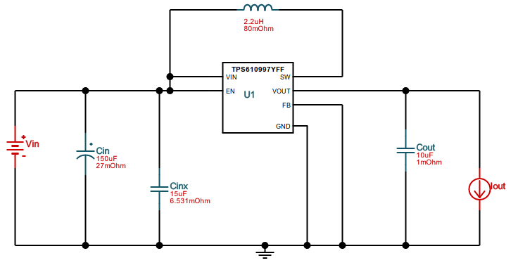
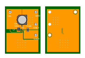
I am in the process of designing a +5V power supply for a hand-held 2xAAA powered device.
When using TI's webench simulator tool to simulate a switcher power supply that I am considering, I noticed on the default schematic for the TPS61099 device that there is a very large capacitor right at the battery input (labeled Cin). It is 150 uF, physically HUGE, and EXPENSIVE ($2.59!). This cap is in addition to the usual moderately sized cap on the input of the switcher (15 uF)
This is my first battery-powered design, so I must be missing something. I'm used to designing products which run off of a 12 or 24V industrial DC bus, and there was never any need for such a cap on the input.
So why is the cap required? It seems that TI is not the only one to suggest this as a reference design, since this answer shows an LT datasheet that shows a similar setup, also for a battery powered design.
Can I safely leave that cap out of my design? Or is there a particular aspect of battery-powered design that requires enormous input power caps? Why can't I rely on Cinx (15 uF) as the only input cap?


