1
\$\begingroup\$

I have an embedded system based on a STM32 ARM Cortex M0+ microcontroller (STM32L051K6) and want to use it to convert an analog sinusoidal input signal into a digital pulse signal and do some SW calculations on the number of pulses (for additional digital busses, like I2C). For the application, it is very important to count every pulse without any loss and forward each pulse with a minimal delay of not more than few tens of microseconds to a digital output pin. One other limitation is the power consumption, and this was one reason for choosing this MCU and operating it only at 4 MHz.

My first approach was to use the ADC with DMA for the input signal to empower a discrimination with a lower and upper threshold, in order to be as flexible as possible for the future, since later in the field, in terms of amplitude (300mV-5V) and frequency (0.5Hz-20kHz) the input signal can vary widely. In other words, it should act as a dynamically programmable Schmitt-Trigger: enter image description here
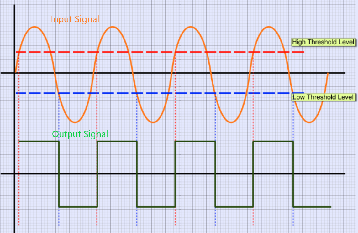
For this, I used the STM32 HAL library. It worked seamless, but quite too slow for my application, the delay between one input and output pulse is significant over 100us and with a quite wide jitter... I also had the idea to use an external circuit to trigger a comparator input of the MCU, but I wanted to evaluate the performance of all available possibilities first, before changing the PCB layout.

What are your impressions of my approach? Does anyone know a better/more performant solution with this kind of MCU?

\$\endgroup\$
12
  • 2
    \$\begingroup\$ You say the input is sinusoidal but then say you want to count every pulse. You also talk about a lower and upper threshold. Please explain what these things mean to you, and how they apply to this problem. \$\endgroup\$ Commented Jan 31, 2019 at 13:38
  • 2
    \$\begingroup\$ Also, if 100usec is too slow, what is "fast enough"? I also think you need to be very specific about what processing you're doing. This seems too vague to answer. I don't know what "transform to a digital pulse" means. Why do you need to count the pulses when you're producing them, and show know what you're outputting. Do you have the pulses on a digital input and you're counting them with a counter? Too vague. \$\endgroup\$ Commented Jan 31, 2019 at 13:41
  • \$\begingroup\$ @ Elliot Alderson: the conversion of the sinusoidal signal to pulse signal should be implemented by the MCU like a "dynamically programmable Schmitt-Trigger", I uploaded a picture which describes that. \$\endgroup\$ Commented Jan 31, 2019 at 15:00
  • \$\begingroup\$ @Scott Seidman: I would say something between 20-30us would be a tolerable latency time inclusively parallel incrementing a counter variable that represents the number of detected pulses (which is accessed via an I2C interface). \$\endgroup\$ Commented Jan 31, 2019 at 15:05
  • 1
    \$\begingroup\$ The HAL (as with many libraries) trades efficiency (in terms of CPU cycles) for both programming simplicity and robustness (although the HAL has been known to do 'unusual' things on occasion). If you are open to adding a front end trigger outside of the MCU you could simply increment one of the internal hardware counters for pulse count; to move an event across to a GPIO quickly may require bare metal techniques. I have implemented a variable threshold trigger using (for all their limitations) digipots. \$\endgroup\$ Commented Jan 31, 2019 at 15:41

1 Answer 1

3
\$\begingroup\$

There is an analog watchdog in the ADC just for this purpose.

From the Reference Manual:

Analog window watchdog (AWDEN, AWDSGL, AWDCH, AWD_HTR/LTR, AWD)

The AWD analog watchdog feature is enabled by setting the AWDEN bit in the ADC_CFGR1 register. It is used to monitor that either one selected channel or all enabled channels (see Table 62: Analog watchdog channel selection) remain within a configured voltage range (window) as shown in Figure 46.

The AWD analog watchdog status bit is set if the analog voltage converted by the ADC is below a lower threshold or above a higher threshold. These thresholds are programmed in the 12 least significant bits of the ADC_HTR and ADC_LTR 16-bit registers. An interrupt can be enabled by setting the AWDIE bit in the ADC_IER register.

So it can generate an interrupt. The interrupt handler should

  • read the last converted value
  • compare it with a threshold value
  • set the output pin accordingly
  • and do the rest afterwards

It would take perhaps 10 to 20 clock cycles. With the interrupt entry latency (15-20 cycles) it should take maybe 10 microseconds at 4 MHz, way less than your goal.

Give the ADC interrupt handler higher priority than any other handler (note that value 0 is the highest priority), and avoid HAL like a plague for time-critical tasks. There are detailed descriptions for every step in the Reference Manual, even some code examples without HAL.

You can store the converted values in memory using DMA, and evaluate them in the background to adjust the thresholds. The problem is that the ADC must be stopped to update the threshold register, and restarted afterwards. You can syncronise that with the interrupt, i.e. doing it in the interrupt handler just after the analog watchdog event.


Using the on-chip comparators with some external circuitry

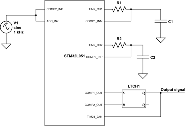
Based on @ScottSeidman's idea in the comments above. There are two comparators in the MCU, they can be used to detect the lower and upper thresholds. Set the compare levels with two PWMs and RC filters, and connect their output to an RS flip-flop to have a single digital output, which can be fed back to a counter input pin.

schematic

simulate this circuit – Schematic created using CircuitLab

\$\endgroup\$
2
  • \$\begingroup\$ You could also just use DIO to take care of the flip flop responsibilities, if the clock ticks can be spared. \$\endgroup\$ Commented Feb 1, 2019 at 16:56
  • \$\begingroup\$ @ScottSeidman if you have the cycles, then you could as well use the analog watchdog, without external components. I'm thinking about (ab)using timers somehow to create a flip-flop. \$\endgroup\$ Commented Feb 2, 2019 at 7:46

Your Answer

By clicking “Post Your Answer”, you agree to our terms of service and acknowledge you have read our privacy policy.

Not the answer you're looking for? Browse other questions tagged or ask your own question.