0
\$\begingroup\$

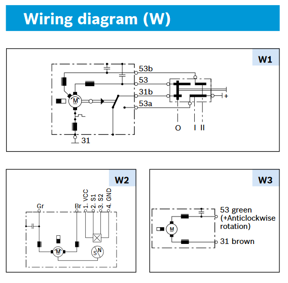
Below is the schematic of a Bosch electric motor:

enter image description here

What are the three double-lined (one thick one thin) elements on the left side? What is the part on the right (black thick lines)? What is the white circle and black triangle exiting the motor on the right?

The complete manual with some symbol explanations is given here on page 6:

\$\endgroup\$
1
  • \$\begingroup\$ Probably a dual speed switch an inertial switch run cap boost current \$\endgroup\$
    – D.A.S.
    Commented Feb 7, 2019 at 19:36

2 Answers 2

4
\$\begingroup\$

This looks like a motor that might be used for windshield wipers amongst other things. There is a nice explanation of windshield wiper motor switching here which clarifies the wiring.

The black boxes on the left are simply inductors (Chokes, "Throttles"). I assume the small line indicates core type possibly. They are likely added to reduce the noise the brushes would otherwise inflict on the system. They act to smooth the current and eliminate the sudden drops in current as the brushes ride over the gaps between contacts.

The white circle and line exiting the motor to the right indicates mechanical action by the motor and will toggle the switch at some point in its rotation.

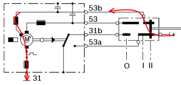
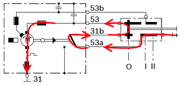
Finally, the black mess to the right can be understood like a sweeping contact. The central white "shaft" is an actuator connected to the left vertical bar "sweeper". As the actuator is moved, it makes contact between the various pins. Shown below are images of the various switch positions showing current flow.

Stopped Switch Position:

stopped

Slow Switch Position:

slow

Fast Switch Position:

fast

Stopped Switch Position with the motor running back to rest position:

coasting

Note: I don't believe the controlling switch is included with the motor, only an example to illustrate the dual speed control.

\$\endgroup\$
0
\$\begingroup\$

The double-lined (one thick one thin) elements on the left are inductors. Not literal components added to the motor, but indicate the inductance of the windings already present inside the motor.

The thick black lines on the right are indicating a mechanical switch. The dashed line below it and "0", "1", and "2" are the positions the switch can be in. Sliding the switch from "0" to "1" would slide the thick vertical bar to the "1" position. Pin 31 is connected to a ground symbol, so it is 0v. The pin with the "+" on the switch, is +DC. So this is a DC motor. It is not very clear from the switch representation, but I bet "+" connects to pin 53 in the "1" position, and pin 53b in the "2" position. So a low and high-speed setting.

The white circle and black triangle exiting the motor is most likely a centrifugal, excessive torque, limit, or over-ride switch. Not very clear. But whatever causes it to activate, flips that switch immediately to the right of it, affecting pins 31b, 53a, and an unlabeled pin on the bottom. This could have a large number of uses, from direction reversing to stopping the motor.

\$\endgroup\$

Your Answer

By clicking “Post Your Answer”, you agree to our terms of service and acknowledge you have read our privacy policy.

Not the answer you're looking for? Browse other questions tagged or ask your own question.