0
\$\begingroup\$

I want to build simple CNC machine, via reusing printer head, connected to arduino. As per motion its all right: I use L298N dual driver, and can control movement direction and speed via PWM, setting appropriate voltages on the pins.

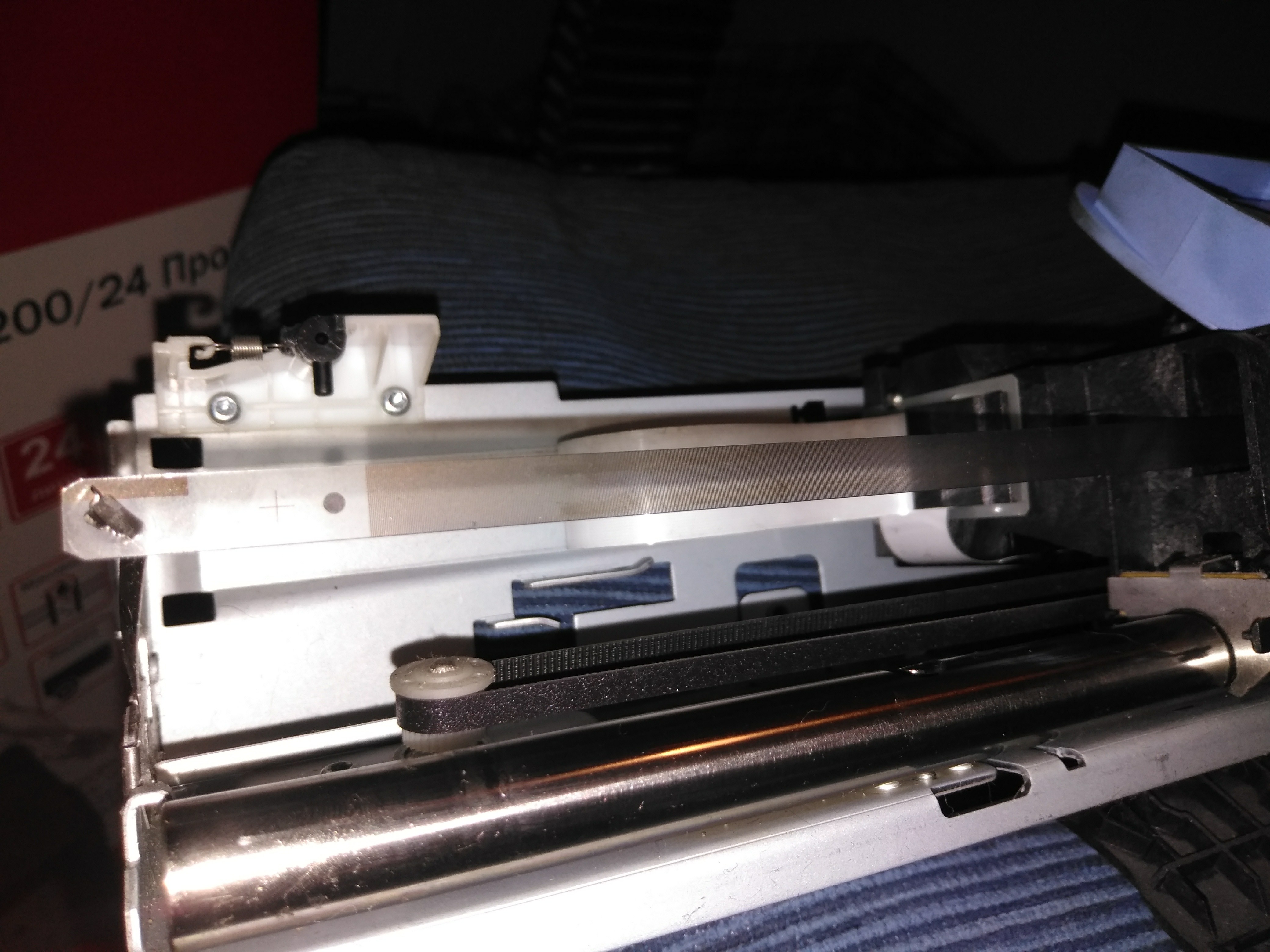
Question is that I need a coordinate system, and printer head had some plastic PET strip with transparent and black stripes. And I guess, an "opto isolator"? (correct me if i am wrong)

My question is how does it work and how to operate this strip "electronically"?

  • Should I set or read voltages? What voltage and at what rate? (arduino is a discrete machine, kind of fixed-timestep "adc sampler")

  • Should I control current, for instance, limit it?

  • Does that operates like led, or a resistor, or a transistor?

PS: Strip is on the photo below:

enter image description here

\$\endgroup\$
4
  • 1
    \$\begingroup\$ no it is not an opto isolator ..... it is an optical slot sensor ..... the two are similar in construction, except that an opto isolator does not have a way to block the sensor mechanically .... it is used for electrically isolating the output from the input \$\endgroup\$
    – jsotola
    Commented Feb 10, 2019 at 18:10
  • \$\begingroup\$ @jsotola I've wondered primarily about pinouts and legs, along with operating voltage and the need for current limiting. \$\endgroup\$
    – xakepp35
    Commented Feb 14, 2019 at 16:47
  • \$\begingroup\$ @jsotola eg 1) Could I use common ground for input and output? 2) What is a safe operation voltage? I want 5 VDC for arduino 3) Do I need to put a input current limiting resistor (like for led) or is it voltage-operated? \$\endgroup\$
    – xakepp35
    Commented Feb 14, 2019 at 17:51
  • 1
    \$\begingroup\$ it is just an IR Led aimed at a photo-transistor ..... you can use a common ground ..... the photo-transistor does not supply power, it is just an electronic switch ..... on an Arduino, wire it same as a pushbutton switch .... enable the internal pullup instead of an external resistor (you may need external resistors if there is too much electrical noise being picked up) ..... forum.arduino.cc/index.php?topic=147722.0 ...... \$\endgroup\$
    – jsotola
    Commented Feb 14, 2019 at 21:03

1 Answer 1

1
\$\begingroup\$

The "optoisolator" is indeed an electro-optical device for reading the stripes on the plastic strip. It most likely has two sensors internally, arranged so that they sense in "quadrature", allowing them to detect not only the amount of motion, but also its direction. The output of each detector is a digital signal that your MCU should be able to handle more or less directly.

In order to use this, you'll have to set up a "quadrature encoder". If your MCU has hardware for this, so much the better; otherwise, you'll have to do it in firmware.

\$\endgroup\$
9
  • \$\begingroup\$ So, theoretically that should have 4 legs - a common ground, a DC input +5VDC for powering light source (without any current limiting), and outputs for channels A and B. And they can output low(<0.6VDC) or high(>2.5VDC) voltages, relative to common ground. And I should just read A and B signals and do some "quadrature.." DSP with those two. Am I Right with that rough guess? \$\endgroup\$
    – xakepp35
    Commented Feb 9, 2019 at 15:00
  • \$\begingroup\$ @xakepp35 Depends on how the output is configured; some of these have open-collector outputs instead of push-pull. \$\endgroup\$
    – Hearth
    Commented Feb 9, 2019 at 15:05
  • 1
    \$\begingroup\$ You'll have to look up the specific part, or make your own measurements, or take a look at (reverse engineer) the original printer board. That's why I said "more or less" -- some signal conditioning may be required, but in any case, it's a binary signal with just two states. \$\endgroup\$
    – Dave Tweed
    Commented Feb 9, 2019 at 15:18
  • \$\begingroup\$ Liked your reply, but "look at (reverse engineer) the original printer board" is some "company secret", which would lead only to "dumping+disassembling firmware". I am Russian, and so is very falimiar with it, but dont want to bother with USA. I want to go my own way from the grounds, ignoring their patented algorithms. I dislike that policy for being "anti-scientific" or "anti-educational" (human="stupid user") - "no datasheets for own assemblies provided, no cartrige refills", so on.. So we should ban that country worldwide, in theory, we not accept it. \$\endgroup\$
    – xakepp35
    Commented Feb 9, 2019 at 17:08
  • \$\begingroup\$ In practics, regardless to politics and policies, i want to ask - "do I need to limit a current, or is just a DC pin voltage is suffient?" and "Does it have a common ground, or is it optoisolated and actually 2 grounds? (3 grounds - there are 2 sensors+emitter, and each is 2pin device)" \$\endgroup\$
    – xakepp35
    Commented Feb 9, 2019 at 17:09

Your Answer

By clicking “Post Your Answer”, you agree to our terms of service and acknowledge you have read our privacy policy.

Not the answer you're looking for? Browse other questions tagged or ask your own question.