0
\$\begingroup\$

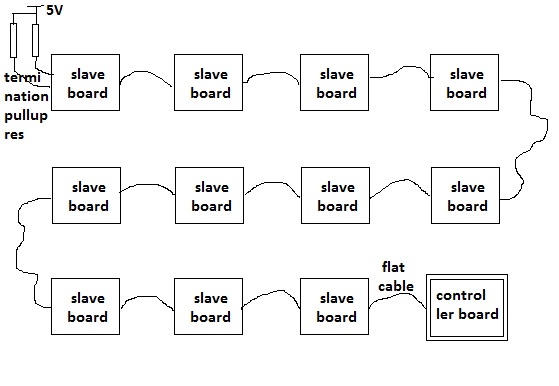
I have a system with an I2C bus wired just like this:

enter image description here

Which one is better: put the termination pull-up resistor at the end of the connection (on the last board), or put the pull-up resistors on each slave board?

I'm having a problem in that initially it worked, but after some time the I2C communication to the board failed and can't be recovered (SCL always stuck low when I observe using a logic analyzer). On each board there's a chip like PCA9685, MCP3424, PCA9674, etc.

\$\endgroup\$

3 Answers 3

4
\$\begingroup\$

You can't just put a pull-up on every board: Your I²C devices need still to be able to pull down the lines, so if you increase the up-pulling by adding more boards, you're making it harder for the I²C devices to use the bus.

Then, adding more boards even without pull-ups on each of them will increase the capacitive load on the bus, up to a level where the bus might simply no longer work, because any one of your chips might no longer to pull down fast enough.

The solution to that is using either a more robust bus (CAN comes to mind), or redriving the bus every couple of boards. With I²C being a bidirectional bus, this is pretty complicated. A solution might be to limit the numbers of boards per bus to something benign (depending on your cable length and boards and chips), and then using a bus extender to drive multiple buses in what will look more like a star architecture than a daisy chain.

\$\endgroup\$
5
  • \$\begingroup\$ Thanks for the advice @MarcusMuller, currently I run the I2C with SCL freq 100kHz, I already tried to reduce SCL freq to 50 kHz, then 25kHz but the problem still occuring. Maybe next I'll try to add delay in between I2C byte transaction. \$\endgroup\$
    – Qrenz
    Commented Feb 18, 2019 at 4:22
  • \$\begingroup\$ That delay very likely won't help. Your bus is too hard to drive, probably at any speed; a delay wouldn't even help if speed was the limit. \$\endgroup\$ Commented Feb 18, 2019 at 7:57
  • \$\begingroup\$ There's actually one extra slot in my controller board that probably could be used for another i2c bus, but the SCL & SDA in the controller side will be pulled up to 3.3V while in the slave boards it will be pulled up to 5V, could it be worked if they are connected? \$\endgroup\$
    – Qrenz
    Commented Feb 19, 2019 at 5:30
  • \$\begingroup\$ no, your bus is too long. I'm afraid this is the last time I'll repeat that. \$\endgroup\$ Commented Feb 19, 2019 at 7:31
  • \$\begingroup\$ "Extra Slot" bro, I mean I'll create another bus and transfer some slave boards to that bus, so the number of boards on one I2C bus will be cut to halve. Still too long? Already cut to halve... \$\endgroup\$
    – Qrenz
    Commented Feb 20, 2019 at 4:28
1
\$\begingroup\$

Consider having lower value pulldowns like 3.3k on the main board, and higher value ~22k resistors on the child boards. Not ideal, but better then one or the other.

As the previous answer noted, you will have an issue as your bus gets larger, with capacitance and eventually all the pulldowns.

\$\endgroup\$
1
  • \$\begingroup\$ Thanks for the advice @MadHatter, as for now the main board has 10k pull up, and I can't replace it because I'm not confident desolder small SMT component, the position of res too is in crowded location. Btw, why is the res value in the main board should be smaller than those on the child boards? \$\endgroup\$
    – Qrenz
    Commented Feb 18, 2019 at 4:20
0
\$\begingroup\$

You may have a situation where one of the devices wants to extend the bus cycle and another device does not like or support that. I will take a swag and assume the lowest resistance your weakest I2C device could drive is about 1.5K. Remember all the resistors on the bus are parallel are parallel. Treat each bus phase SDA and SDL separately when calculating the resistance. If that bus is longer than about 1 meter (yard) it will not be reliable but it is a great antenna for receiving electrical noise.

The I2C bus was not designed for inter module communication. I would seriously consider another method of running your bus, There are many but My favorite is to use Cory Fowlers CAN library for Arduinos, it does not take much code on your part to implement it. The MCP2515 module works very well, has the CAN controller and bus transceiver on it. You will need a SPI to communicate with it.

You can use CAN on other systems but you will need a different library. You can use CAN with a 3V3 or 5V system no additional voltages required.

\$\endgroup\$
1
  • \$\begingroup\$ If a slave wants to extend clock, only the master needs to support it, not the other devices. 1 meter bus itself is not a problem if the cabling is good, but we don't know that (HDMI, DVI and VGA cables are much longer). The post is also almost 4 years old, I don't think we ever know how it worked out. \$\endgroup\$
    – Justme
    Commented Nov 7, 2022 at 17:24

Your Answer

By clicking “Post Your Answer”, you agree to our terms of service and acknowledge you have read our privacy policy.

Not the answer you're looking for? Browse other questions tagged or ask your own question.