9
\$\begingroup\$

This is the opposite/complement of my previous question, which concerned measuring the precise position of an object as it is moved/drawn by someone over a short duration. Assuming I use one of @Rocketmagnet's suggested approaches (probably using linear encoders), next:

Suppose I have tracked/recorded the X-Y position data as an object is moved arbitrarily through some pattern across a 2-D plane by someone:

Goal: Now I would like the object to replicate that same recorded movement pattern, i.e., I would like the object to move through those same X-Y positions -- but automated this time.

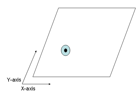
In other words, I would like the system to carry/displace the object from the recorded (X1, Y1) to (X2, Y2) to (X3, Y3) and so on. Again, completely constrained to a 2D plane/surface, like so:
enter image description here

Constraints:

  • I would like fairly controlled/accurate movement of the object, with no greater than 0.5mm error.
  • The domain of points for the object to move will extends across a 30cm X 30cm square.
  • Exact duration/path between points is NOT critical -- since I will have a fairly well-populated point set (so it will already be pretty close to continuous movement).

The one potential solution I have considered for this (and I think one that is easy to implement) is to use motors placed on the edges but somehow connected to the object. But I am not sure how to connect them in a way that allows 2 degrees of freedom simultaneously, and moreover, I'm not sure how/if it's possible to attain the desired movement accuracy using motors.

So my question is: What are potential methods I can try for this kind of accurately controlled 2-dimensional movement? There are very few physical limitations on my setup as it currently stands, so I am open to toying with (reasonable) implementations of any level of complexity!

One piece of good news is: Since I will have a precise measurement/tracking system (from the previous question), it would be possible to integrate feedback / calibrate during the movement, which I suppose will be essential if I want to assure the 0.5 mm maximum error.

EDIT: In case the exact application is of interest: The system is my attempt at a simplified electronics-art demo of action-replication, i.e., a person's action is recorded and it is then duplicated either after a period, or on a duplicate system nearby. I initially tried working with shape memory alloys (nitinol specifically), but recording a 3-D movement of a multi-point shape was not easy (FAR from it!), hence my simplification to a "single-point" object across a 2-D plane.

\$\endgroup\$
5
  • \$\begingroup\$ Can I ask what this system is going to be? If I knew, it might help me provide a better answer. \$\endgroup\$ Commented Sep 29, 2012 at 15:00
  • \$\begingroup\$ Also, since you're into robotics, you might be interested in joining our Robotics Stackexchange Proposal \$\endgroup\$ Commented Sep 29, 2012 at 15:06
  • \$\begingroup\$ @Rocketmagnet: Added the description above. And the Robotics Proposal: Thanks, I'm in; and it seems to be moving towards 100% extremely fast! \$\endgroup\$
    – boardbite
    Commented Sep 29, 2012 at 15:23
  • \$\begingroup\$ If this is an art demo, do you really need such accuracy? I think what you really need is resolution. For example, if the drawing was replicated perfectly, but 2mm offset, would that be a real problem? \$\endgroup\$ Commented Sep 29, 2012 at 18:26
  • \$\begingroup\$ @Rocketmagnet: In comparison to the 30cm X 30cm, I think 0.5mm sounds a little extreme indeed. My thought was if I began working with a method that is theoretically capable of high precision, then my implementation in reality would surely magnify the error a bit, getting it to the 1 or 2mm in the end. \$\endgroup\$
    – boardbite
    Commented Sep 29, 2012 at 18:29

4 Answers 4

8
\$\begingroup\$

You might as well combine the measurement and replication into one system. Let me start with my previous answer to your question: Idea 4

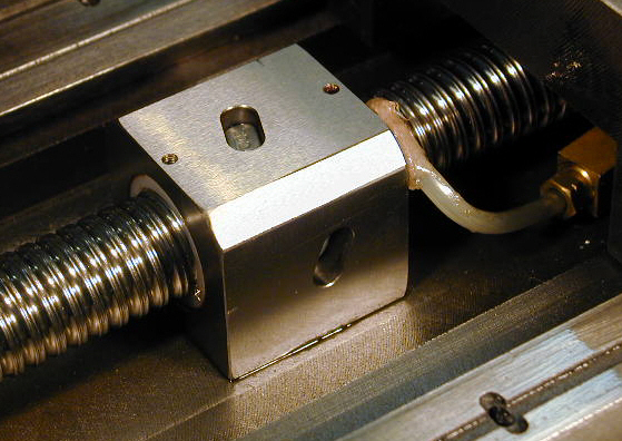
You already have linear bearings and encoders set up to measure the motion of the object. Now all you need to do is to actuate those bearings. Normally, if you were building something like a CNC milling machine, and you wanted to actuate linear motions, you'd use a ballscrew and a stepper motor.

Ballscrew

The problem with these is that they are not back-drivable, and therefore you won't be able to move the object yourself. Two options:

  1. Add force sensors (using strain gauges). Now the system can detect you pushing on the object, and it will drive the motor to create the illusion that there's no motor there at all. This can work extremely well if you do it carefully, and if the motor is fast enough. This is known as active compliance.
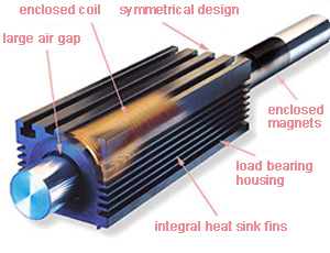
  2. Use linear motors. These are completely back-drivable when unpowered.

Linear motor


The good news is that, if you can afford it, you can buy complete linear motor motion systems from companies like Aerotech or Baldor Motion. Alternatively, you can ask a small robotic engineering company to build you the whole system. Again, these systems are very accurate. They're used where 0.01mm accuracy is a common requirement, and even 0.001mm accuracy (but then you really need a temperature controlled environment).

\$\endgroup\$
2
  • \$\begingroup\$ Leadscrew systems can be backdriven if the lead angle of the screw is low enough. I have a Kerk ballscrew/nut combination that I can easily backdrive by hand. \$\endgroup\$
    – lyndon
    Commented Sep 29, 2012 at 17:19
  • \$\begingroup\$ @Rocketmagnet: Wikipedia defines this term "backdriving" as: "the use of a component in reverse to obtain its input from its output". Can you explain what you mean by "[stepper motors] are not back-drivable", as in what is the relevance here? In my demo, the human will NOT move the object simultaneously while the system is moving it, or vice versa (in fact, it may be possible that the auto-replicating section of my demo would be completely separate from the human-movement section) \$\endgroup\$
    – boardbite
    Commented Sep 29, 2012 at 18:22
7
\$\begingroup\$

Based on your edit, I think that my solution involving linear motors is a little over-the-top. Your application is to simply an art demo which reproduces someone's drawing. While this needs to have good control and resolution to make a faithful reproduction, it really doesn't need the accuracy you originally specified.

First we should clear up some often misunderstood terms: Accuracy, resolution and repeatability. I suggest reading the Wikipedia article Accuracy and precision.

What you need is good resolution in the measuring part, probably 0.1mm. You probably need fairly good repeatability, again, let's say 0.1mm. However, you don't really need great accuracy. For example, if the reproduction always came out identical to the original, but 3mm offset to the left, then I'm sure you'd be happy. Likewise, what if the reproduction was 0.5% too large? Would that really be a problem?

For the measurement phase, I recommend using the string pots. They're simple to set up.

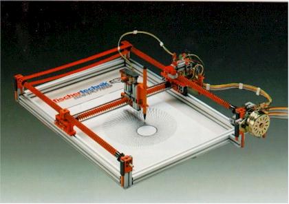
For the reproduction phase, what you want to make is a plotter.

Plotter

These are not difficult to make yourself, and people make them all the time. Check out Contraptor Plotter for example. Or the many other examples on the web.

\$\endgroup\$
5
\$\begingroup\$

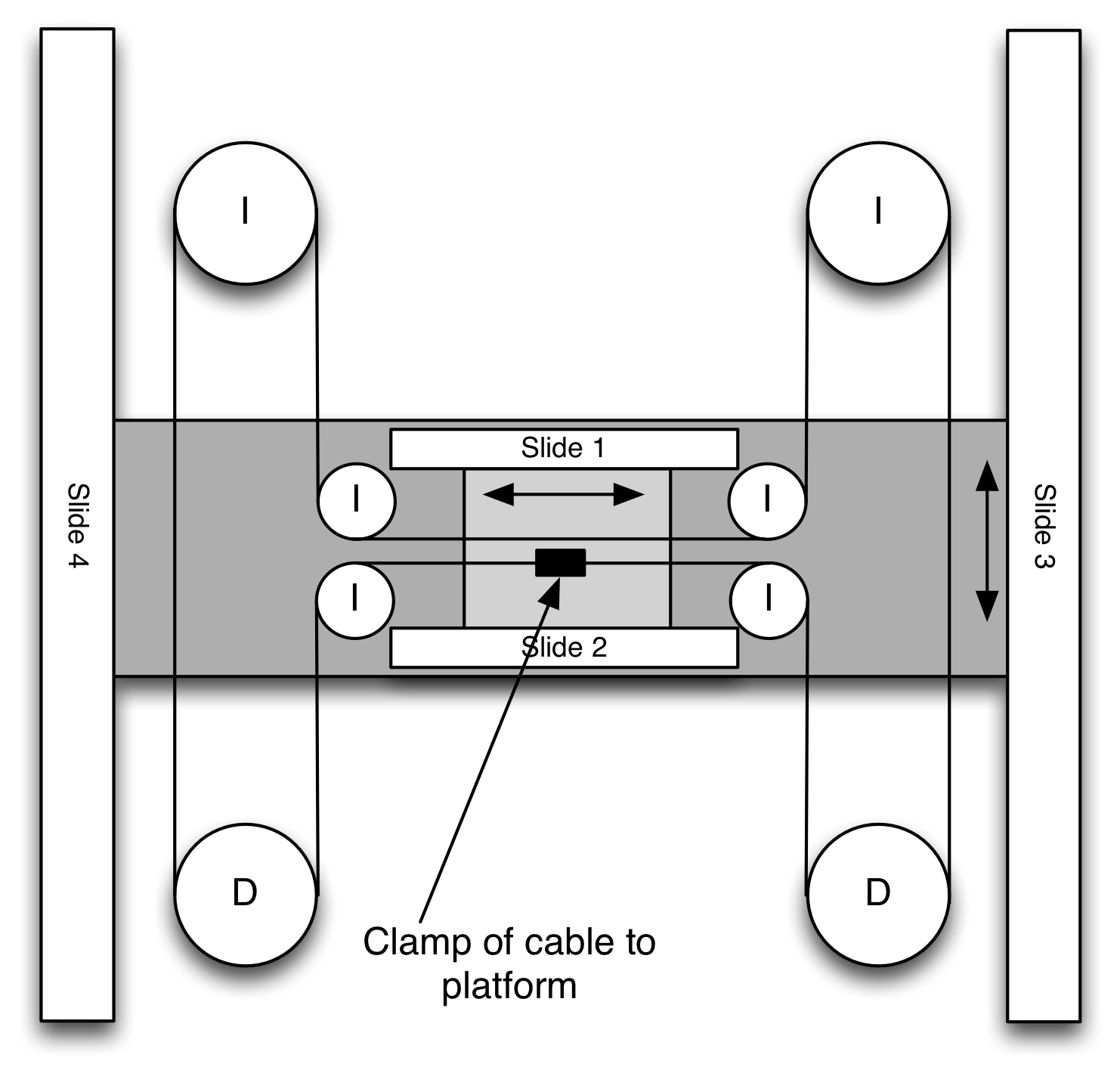
enter image description here This one of the cleverest solutions for this I remember seeing: "I" = Idler "D" = driven Dark gray platform is attached to slides #3,4 Light gray platform is attached to slides #1,2 which are anchored to Dark gray platform
Cable is a thin line wrapped around the idlers and pulleys in the figure of an "H"

Cable is anchored to light gray platform (shown with arrow)

If driven pulleys are driven in opposite directions (CW and CCW) at same rate. Bigger platform translates up and down the page.

If driven pulleys run in same direction (both CCW say), smaller platform run on top on big platform left and right on page.

Changing rates and directions of driven pulleys means you can translate in any direction you want.

Use stepper motors on "D" pulleys.

\$\endgroup\$
4
\$\begingroup\$

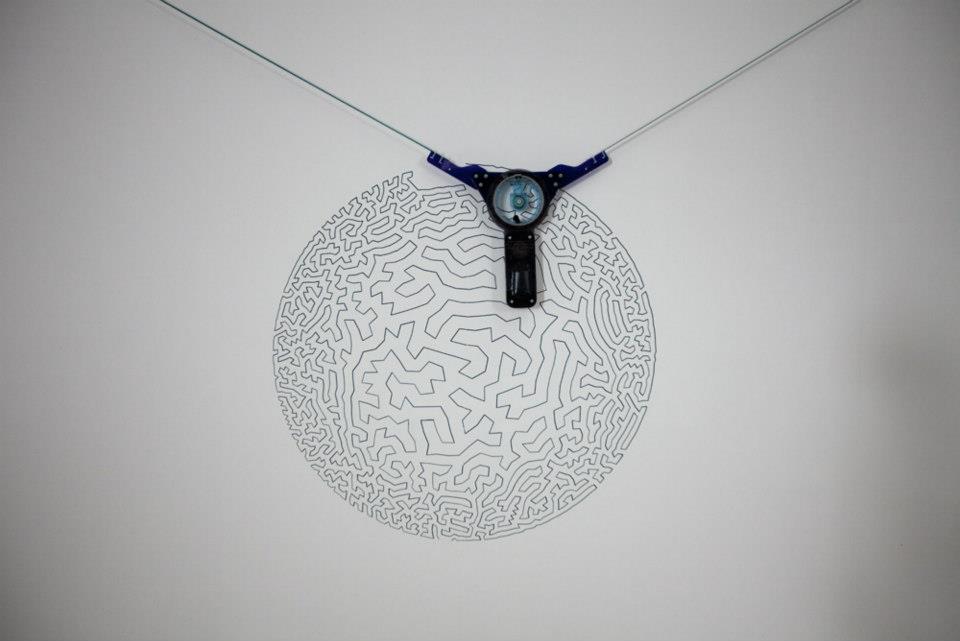
One more way to implement a 2D plotter is this:

2D Plotter

It was used to plot some large drawings at the Mind Out festival of the mind.

As you can see, it's very similar to the 2D measurement using string pots, replacing the pots with motors.

\$\endgroup\$

Your Answer

By clicking “Post Your Answer”, you agree to our terms of service and acknowledge you have read our privacy policy.

Not the answer you're looking for? Browse other questions tagged or ask your own question.