0
\$\begingroup\$

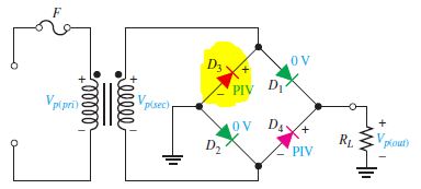
I'm having trouble knowing when is the cathode negative or positive and vice verse ( I'm not talking about the symbol ) I'm saying, when do the polarities change? For example, look at these 2 pictures

enter image description here

That highlited diode oddly has a positive cathode, but normally the cathode is the one supposed to be negative, so I don't know when to decide the polarity of each diode.

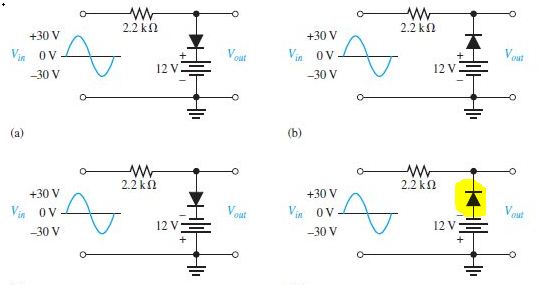
In the following picture, what determines the polarity of the diodes and how can I understand it?

enter image description here

\$\endgroup\$

2 Answers 2

1
\$\begingroup\$

In general, you can consider a diode to be open-circuit when the voltage on its anode is less than that on its cathode.

schematic

simulate this circuit – Schematic created using CircuitLab

Figure 1. (a) Positive half-cycles. (b) Negative half-cycles.

The bridge rectifier situation is easy! Remove the reverse biased diodes on alternating half cycles. The 'dot' in the captions refers to the dot on the transformer secondary winding.

In each of the other circuits you need to work out at what input voltage the diode becomes affects the circuit. Draw that line on the input waveform and you'll be most of the way to your answer.

Load the image into an image editor, mark up the positions as I've described then mark up the resultant output voltage. (Just overlay both on the blue sinewave that is in the question.) Post your effort into your question and we'll see if you are understanding it correctly.

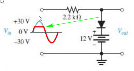
Example for (a):
enter image description here

*Figure 2. (a) When the input voltage exceeds 12 V the diode will conduct and current will flow into the battery. The output will be clamped at 12 V. At all other times the output will follow the input.

Now, you do the same for the other three and post your results in your question.

\$\endgroup\$
2
  • \$\begingroup\$ Is this correct? ibb.co/MDXJnn6 \$\endgroup\$
    – khaled014z
    Commented Feb 24, 2019 at 21:19
  • \$\begingroup\$ See the update to my answer. \$\endgroup\$
    – Transistor
    Commented Feb 24, 2019 at 21:36
3
\$\begingroup\$

Your first drawing shows the polarity of the voltage across the diode when the top terminal of the transformer is positive, and diodes D3 and D4 are reverse biased, and not conducting.

D1 and D2 will have anode positive, and be conducting - they are apparently ideal diodes as they are shown with zero volts across them.

When the top terminal of the trasnformer is negative, D3 and D4 will have the anodes positive, and will be conducting, while D1 and D2 will be reverse biased, and not conducting.

The diode polarities in that drawing are the actual voltages applied to the diodes, not some innate properties of the diode.

\$\endgroup\$
6
  • \$\begingroup\$ Just repeating this again for emphasis: "The diode polarities in that drawing are the actual voltages applied to the diodes, not some innate properties of the diode." Anode and cathode are terminals on the the diode. If you make the anode positive and the cathode positive it will behave a certain way, if you reverse the polarity it will behave another way. Diodes that are meant to do their job by conducting current (most diodes, LEDs, schotky) will do so with a positive anode/negative cathode. Diodes whose job is to clamp voltage (zener, TVS) do their job with negative anode/positive cathode. \$\endgroup\$
    – DKNguyen
    Commented Feb 24, 2019 at 20:23
  • \$\begingroup\$ Yes I only care about the potential difference applied on the diode, since D3's cathode is positive by the top terminal of the transformer, can I use the same logic and apply it to the last circuit in the second picture and say that the cathode of the diode is positive with respect to the anode? \$\endgroup\$
    – khaled014z
    Commented Feb 24, 2019 at 20:26
  • \$\begingroup\$ By "last circuit", you mean bottom right? \$\endgroup\$
    – DKNguyen
    Commented Feb 24, 2019 at 20:28
  • \$\begingroup\$ Its highlighted now, the bottom right one, the problem that I'm having is when applying KVL, I seem to get some sign wrong and end up with a false output voltage \$\endgroup\$
    – khaled014z
    Commented Feb 24, 2019 at 20:30
  • \$\begingroup\$ You need to be very careful in your language here since you are dealing with an AC input. The 12V battery biases the entire AC input waveform by moving the graph up by 12V. So you have a net of 42V being applied in the first half cycle, and -18V being applied in the second half cycle. So in the first half cycle, positive cathode/negative anode. In the second half cycle, negative cathode/positive anode. \$\endgroup\$
    – DKNguyen
    Commented Feb 24, 2019 at 20:39

Your Answer

By clicking “Post Your Answer”, you agree to our terms of service and acknowledge you have read our privacy policy.

Not the answer you're looking for? Browse other questions tagged or ask your own question.