2
\$\begingroup\$

I need to connect a cars fuel sender(ohms) to a analog input on a GPS tracker (volts)

Here's the catch, in our tests most fuel senders we worked with seem to send the data as ohms/resistance

However, the GPS trackers analog inputs require volts (Generally gps trackers take 0.5 to 5.5 volts as their analog input)

In rare cases, we found some fuel senders use volts, but most use resistance. Therefore I need to find a gadget (ideally one that already exists I could buy off the shelf) that will take the input from the fuel sender, and convert it to volts, so I can connect it to the gps tracker.

I've looked into arduino stuff, but it's a bit overkill for what i need, so was hoping a micro controller already exists for such a task (if micro controller is the correct phase) - Ardunio coding is not an issue for me, and have done some C coding for a car tuning company previously, so am familiar with the basics, but the price/setup time is quite high for this application.

The only curve ball here is that each fuel sender might send wildly different min and max ohms values from the fuel sender due to each car manufacturers fuel sender being made for their own gauges Once data is in the software we can manipulate the readings easily to show the fuel level of the vehicle (notably the massive variation in data on a bumpy road)

So my questions are

  1. Are there other things I may have not considered with the above project?
  2. Is there an off the shelf micro controller that might do this, if so what is its name (for help searching online). Also, are there any website online that might sell such a device
  3. if the above does not exist, can anyone suggest what I would need to do to create my own one.
\$\endgroup\$
10
  • 1
    \$\begingroup\$ Is the sender still connected to the car's fuel gauge? If so you should measure the voltage from the sender to ground when empty and full. Add that info into your question. It may make the solution rather simple. \$\endgroup\$
    – Transistor
    Commented Mar 1, 2019 at 14:32
  • 2
    \$\begingroup\$ If constant current flows through the sender element and its resistance changes in response to fuel level, then you convert resistance to voltage by Ohm's law V = IR (y = m*x, where x is your resistance). You may consider checking out RTD reading circuits. The idea is similar. That said, multimeters don't really measure resistance; they typically measure voltage across a resistance by forcing a current through it. \$\endgroup\$
    – Bort
    Commented Mar 1, 2019 at 14:37
  • 1
    \$\begingroup\$ There are plenty of small development boards using ATtiny microcontrollers, that can be programmed with the Arduino IDE, but are only an inch square or smaller. The issue is the conditioning of the signal at the input. These senders have a resistance of typically tens to hundreds of ohms (most are wire resistive elements for robustness), so are going to need either a divider running at a current that gives a reasonable voltage, and ideally fed by a regulated source, or some amplification if you want to run at lower currents. \$\endgroup\$
    – Phil G
    Commented Mar 1, 2019 at 14:38
  • 2
    \$\begingroup\$ The relationship between resistance and tank level is not linear for most designs, so you'll also need to use some sort of lookup table if you want to produce a linear output. \$\endgroup\$
    – Phil G
    Commented Mar 1, 2019 at 14:40
  • 1
    \$\begingroup\$ @Transistor we are looking for a blanket approach, we have the software, and support over 1000 gps trackers, so the GPS trackers will all be different, but generally the analog inputs on all these devices accept between 0-5v as an input. Also we'll want it to work on any car, so to answer your question yes, but I would probably needs to get a range of different fuel sender values min/max \$\endgroup\$
    – Quade
    Commented Mar 2, 2019 at 3:59

1 Answer 1

1
\$\begingroup\$

The "best" solutions always come from the "best" specs in the question.

e.g. At a minimum, it requires a definition of the transfer function for gain, Offset, linearity and desired output Voltage range with tolerances for climatic range and supply tolerances.

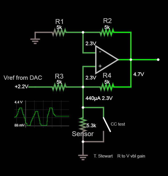
This uses a linear gain-controlled DAC Vref to adjust a constant current source thru the sensor using Rail to Rail OA's from a single supply.

For example

enter image description here

\$\endgroup\$
5
  • \$\begingroup\$ thanks, as i mentioned above i've since found out each fuel sender varies between 0-250 ohms, but it could be 0-90, 240-33 etc I'm looking for solution that will work on any ohm range fuel sender, if this is impossible I guess i would have to have a dip switch solution with presets, or a way to manually configure max and min ohm on the device, so i can apply the calculation? \$\endgroup\$
    – Quade
    Commented Mar 2, 2019 at 6:26
  • \$\begingroup\$ Whatever you do if you don't have specs in your design or question here, there's not much more I can say. \$\endgroup\$
    – D.A.S.
    Commented Mar 2, 2019 at 6:38
  • \$\begingroup\$ understood, what specs exactly would should I be getting? all I really know is the ohm range of majority of senders and that the trackers work on input of 0-5v \$\endgroup\$
    – Quade
    Commented Mar 2, 2019 at 10:05
  • \$\begingroup\$ Specs are specific values you can design towards and verify for the function output you need \$\endgroup\$
    – D.A.S.
    Commented Mar 2, 2019 at 10:06
  • \$\begingroup\$ Would that be something like: Fuel sender sends 0 ohm when full tank/sender on max, and 90 ohms when fuel sender on min When reporting full, it should be translated to 0.5v and when empty 5v ? I'm obviously not at the level you are, so if i need to throw myself into some research, please suggest some areas I should focus on \$\endgroup\$
    – Quade
    Commented Mar 2, 2019 at 10:17

Your Answer

By clicking “Post Your Answer”, you agree to our terms of service and acknowledge you have read our privacy policy.

Not the answer you're looking for? Browse other questions tagged or ask your own question.