I am making a 12 volt regulator for a solar panel to power an audio amplifier. I already have a switching regulator for most application but it is very noisy for amplifier even with a lot of filtering. The amplifier draws over 3 amps on full load.
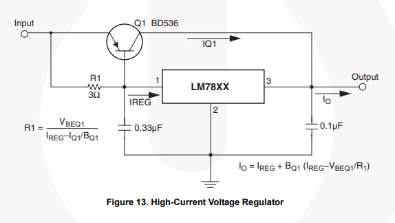
I want to build a regulator using 7812 with series pass transistor for higher current as shown in the datasheet, page 20.
http://www.mouser.com/ds/2/149/LM7812-461970.pdf
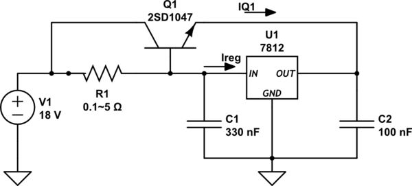
I made the same circuit as shown in the datasheet and used the 2SD1047 as Q1
https://www.st.com/resource/en/datasheet/2sd1047.pdf

simulate this circuit – Schematic created using CircuitLab
But as I connected it to my bench power supply set to 18V I was not able to get a regulated output. It just showed ~2V less then the input voltage.
At 18V no load I got 16V output, 0.5A load 15V and 3A load 12V. I tried different values of R1 calculated by the formula shown in the data sheet.
Is the output voltage affected by the the value of R1?
Please Help.

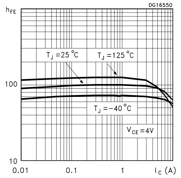
 While calculating R1 I assumed the value for Ireg to be 0.1A, Beta of transistor to be ~95, and IQ1 to be 3A, when that didn't work I tried a bunch of different values of resistors with the same results.
The LM7812 works great when no series pass transistor is attached. And the transistor is good too.
I already have a switching regulator and I also have a higher current linear regulator so don't suggest them please. I want this circuit to work, and I also want to understand this circuit further so if you could point me to other learning material concerning this circuit then that would be great. The only thing I had to work with was the datasheet. Thanks
PS: SOLVED!! My mistake, I connected a NPN BJT instead of PNP.


