You can't have a 1st order bandpass or bandstop, so he must've meant to combine the two 1st orders to give a resultant 2nd order. Then, if you account that a Butterworth lowpass prototype is
$$H(s)=\frac{1}{s^2+\sqrt2s+1}$$
then the resultant bandstop would be
$$H_1(s)=\frac{s^2+1}{s^2+\sqrt2s+1}$$
For the second one, you have to ensure that the transfer function doesn't attenuate ad infinitum, and that also has to happen for a specific bandwidth, in a bandstop configuration. So introduce the \$s\$ term in the numerator so that the ratios of attenuations are ½ at the desired frequency, and 1 in rest:
$$H_2(s)=\frac{s^2+\frac{\sqrt2}2+1}{s^2+\sqrt2s+1}$$
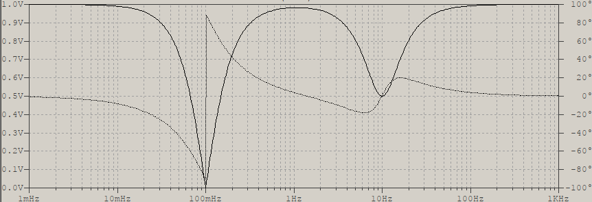
If you plot the frequency response of \$H_1(s)H_2(s)\$, with \$f_1=0.1\text{Hz}\$ and \$f_2=10\text{Hz}\$, this is what comes up:

Notice that due to the relative proximity of the center frequencies and the low orders, the filters interact with each other to give a less than unity response at \$1\text{Hz}\$, but this is to be expected. Also, if your teacher actually wants to fulfill the requirements as seen in the picture, an order (much) greater than 2 would be needed. How much? How to build them? That's for you to figure out. Note that I also didn't include explicit bandwidth definitions for them, I'll also leave that detail to you, it should come out easy from frequency transformations.
[edit for the comment]
To get to this 2nd order bandpass, or bandstop, you start from the 1st order lowpass prototype:
$$H(s)=\frac1{s+1}$$
and carry on with frequency transformations, which generates a bandpass/bandstop having a central frequency and a bandwidth. For example, for a bandstop you'd have:
$$H(\frac{BW s}{s^2+\omega_0^2})=\frac{s^2+\omega_0^2}{s^2+BW s+\omega_0^2}$$
which, represented as a generic 2nd order transfer function, is:
$$H(s)=\frac{a_2s^2+a_1s+a0}{b_2s^2+b_1s+b_0}$$
but with \$a_1=0\$. Some use \$b\$ for numerator, it doesn't matter, really, adjust accordingly. In simple terms, the \$a_1\$ and \$b_1\$ terms define the quality factor, so for the case of interest, bandstop, the quality factor is infinite in the numerator (\$a_0\rightarrow 0\$), and the ratio \$\frac{a_1}{b_1}=0\$, which shows the attenuation at the central frequency. If you could force a specific attenuation, you would have to impose a value for \$a_1\$, and for this case, in particular, you need minimum ½, so then the ratio becomes:
$$\frac{a_1}{b_1}=\frac{a_1}{\sqrt2}=\frac12 \Rightarrow a_1=\frac{\sqrt2}2$$
Don't forget that this is valid for a 2nd order transfer function, for higher orders it gets messy: you no longer have a lowpass prototype from which you can derive the transfer function, you have a shelf lowpass, which is a different thing. But the frequency transformations go just for any other case, it's just that the result will be more "exotic".


