4
\$\begingroup\$

Is it necessary to have impedance matching for short PCB traces if the frequency is lower than say 100MHz ? I've read somewhere that for a trace to be considered a transmission line it should have a length greater than 1/8 of the wavelength of the frequency, and somewhere else greater than the wavelength, not sure which one is more accurate ?

Anyway, assuming that it's 1/8 of the wavelength, at 100MHz the wavelength is 3000mm so it's not necessary to match the impedance for traces shorter than 375mm (3000/8), am I correct here ?

\$\endgroup\$

2 Answers 2

8
\$\begingroup\$

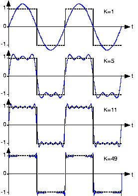
Forget about clock or signal frequency. Think about edge rise time instead. A perfect square wave of, say, 320 Hz actually contains much higher frequency components:

Square wave spectral content

You can see frequency components going right up to 2000 Hz (and they go beyond too). But if you slow the rise time of the square wave, then you actually remove these high frequency components.

Square Wave components

As we add higher and higher frequency components, we can see the rise time of the wave getting shorter and shorter.

To decide what frequencies your signal contains, look at the rise time on an oscilloscope.

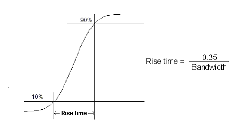
Rise time

The rise time of a signal is usually considered to be the time taken to go from 10% to 90% of the amplitude. Once you have taken this measurement, the maximum frequency you should worry about is about:

freq = 0.5 / rise time

A 100MHz clock will be a big problem if the rise time is 10ps!

\$\endgroup\$
1
  • \$\begingroup\$ So the fast rise time causes the high frequency components right ? also, I've looked at the datasheet of one of the modules and its rise time is 6ns, so this means the highest frequency I should worry about is around 83MHz, right ? still on the safe side, don't you think ? \$\endgroup\$
    – mux
    Commented Oct 3, 2012 at 17:16
3
\$\begingroup\$

As with many things, the answer depends on the specific application.

The 1/8 wavelength rule of thumb generally works, but be sure you're considering all of the frequencies in the signal. This is fairly straightforward for a narrowband RF signal, but if you're talking about a digital signal with fast edges, the relevant frequencies extend to 20× the system clock frequency or more. This can reduce your "safe distance" to just a few inches.

Also, consider whether the PCB trace is simply connecting a source and a load on the same board, or if it's part of a longer transmission line, perhaps going off-board through a connector. In the latter case, any impedance mismatch, no matter how short it is, is going to cause signal reflections in the overall path.

\$\endgroup\$
1
  • \$\begingroup\$ Thanks for pointing that out, especially the second part, I do have both cases on one board. \$\endgroup\$
    – mux
    Commented Oct 3, 2012 at 15:35

Your Answer

By clicking “Post Your Answer”, you agree to our terms of service and acknowledge you have read our privacy policy.

Not the answer you're looking for? Browse other questions tagged or ask your own question.