2
\$\begingroup\$

I have a couple of batteries with original main feeds connected to them. I want to add another battery in parallel, without touching the main feeds.

Setup 1 in the image below shows the current setup, with the exception of the single battery on the right to be added. This battery is a little further than the couple of batteries on the left.

I'm not sure if setup 1 (which requires less work) will compare to setup 2 which is something I'd see recommended. Will I get more resistance with setup 1?

Edit (for dimension): Let's say the distance between the old batteries and new battery is 2 meters: Setup 1 will use 5 meters of cable; Setup 2 will use 8 meters of cable.

2 setups of battery in parallel

\$\endgroup\$
6
  • 1
    \$\begingroup\$ If the contact and cable resistance is much less than the battery ESR it makes no difference. If you don't know that answer, no one can tell. \$\endgroup\$
    – D.A.S.
    Commented Mar 15, 2019 at 4:19
  • \$\begingroup\$ Which is to say if your conductors are adequately sized, you'll be fine either way, but do note that to minimise copper weight for required wire, you should minimise wire length, and when you have a daisy chain of parallel connected devices like this to minimise, if one wire has a larger current than the other(connecting your load across opposite ends as in setup B prevents this being an issue), minimising length becomes more of a priority. Setup A has lower total wire length, but does not have this battery balancing property. I'd go with setup B and/or embiggen the wires. \$\endgroup\$
    – K H
    Commented Mar 15, 2019 at 4:49
  • 1
    \$\begingroup\$ @KH if the layout of bottom right is used in both cases then shortest length is B... \$\endgroup\$
    – Solar Mike
    Commented Mar 15, 2019 at 4:57
  • 1
    \$\begingroup\$ @SolarMike Good point. I see no merit to setup A then. \$\endgroup\$
    – K H
    Commented Mar 15, 2019 at 5:04
  • \$\begingroup\$ @KH Thanks for the helpful response! I was looking through this useful website and was surprised to see the resistance buildup from the first method that they mentioned. That's why I'm not sure how the first setup will perform. But regarding the length of the cables used (they're all about the same size), the first setup will require only 5 meters. The second one will require about 8 meters, as 4 cables are travelling to the new battery which is a couple of meters away. \$\endgroup\$
    – Andy H
    Commented Mar 15, 2019 at 6:07

2 Answers 2

1
\$\begingroup\$

You haven't put dimensions into your big sketches, whose relative lengths seem to be contradicted your little sketches, so it's not possible to tell.

If the big diagram is wider than it's tall, so if the new battery is a long way from the original pair, then setup 1 uses physically the least length of cable, and will have lowest overall resistance. However, the new battery will share less of the load, especially a high current load, due to the voltage drop on the cables. This will still be 'better' than without the third battery.

A setup you've not shown is to connect the third battery directly to the feed terminals. This may use less total cable than setup 2, will result in better balancing than setup 1, and provide the best overall low resistance. However, best balancing will be had with setup 2.

\$\endgroup\$
1
  • \$\begingroup\$ Very helpful! Added dimension as suggested. I see where you're getting at with the new battery sharing less of the load, which is something I was worried about since most recommended setup has opposite ends. I wanted to connect the feed directly to the third battery, but there's only a restricted space to work with. It's hard to see where are all the multiple feeds are coming from to be routed elsewhere. \$\endgroup\$
    – Andy H
    Commented Mar 15, 2019 at 8:23
0
\$\begingroup\$

First, just an explanation of why opposite end connected loads will help balance the battery bank: An image of three lead acid batteries connected in parallel with load connections at opposite ends.  The batteries are arranged vertically with negative posts to the left.  Resistance of wires connecting the batteries are marked as 10 ohms for each wire from the top battery to the middle one and 5 ohms for each wire from the middle battery to the bottom.  The top battery provides positive load connection, the Bottom battery provides negative.  Internal resistance of the batteries is represented by an un-valued resistor drawn between the two posts of each battery.
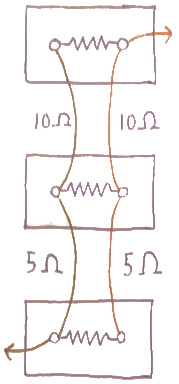
This diagram illustrates the advantages to this wiring arrangement. So long as each pair of conductors from battery to battery is equal, the load sees the same resistance between it and each battery. Just start at either load connection point and follow the shortest path through any battery. Disregarding the internal resistance which is only shown to illustrate the connection, you will have 15 ohms, even if the distance between the batteries varies.

In addition to this precaution, if your batteries are lead acid and of a type you can easily maintain, perform maintenance on the old ones when you add the new one(check and top up the cells) and if you don't already have one, arrange a schedule of routine maintenance.

If they are sealed or non lead acid, consider replacing the original two when you add the third. Lead acid and NiCad are probably most tolerant to skipping this, but if using aged batteries with new ones, at the very least you should monitor them regularly.

Now, if the batteries and load connection are in any other arrangement, such as having the load connected to the same battery, any other battery in the bank will certainly have more resistance between itself and the load. This resistance will prevent that battery from discharging as quickly, So the closer battery to the load will go into a deeper state of discharge before a given voltage is reached, causing greater wear, etc. The more resistance and volt drop difference, the more aggravated this will be. To minimize the effect you might have to keep the volt drop orders of magnitude lower by using much larger wire so that instead of being balanced, volt drop is negligible.

The remaining flaw with the end connected arrangement is that if each battery is providing equal current, the interconnection wire closes to the load connection point carries 2/3 of the load current, and the wire farther away carries only 1/3 load current. If the difference in conductor length was as great as in the diagram, a 2:1 ratio, there will still be some difference in the voltage drops between each battery and the load. Your Setup B, though it has longer total length and may require larger wire for that reason, is likely the best possible arrangement because it promotes balance in the lengths of the conductors between batteries.

Now all that remains is to figure out what size wire you need. Figure out what the resistance of the original wires was using a wire size chart that has resistance in ohms per unit length or calculate based on cross sectional area. Now figure out what length your wires must be to connect all 3 batteries as in setup B while keeping the length of all 4 of them as similar as possible. Then calculate how much resistance per unit length can be tolerated by dividing the old total resistance by the new length. Then return to the wire chart and check what size wire you need. Note that two of the wires carry twice the current of the other two, so there will be some difference in voltage drop, but the current through each battery must pass through one wire of each type so they stay balanced.

While you're at it you could check your maximum total load current and figure out how much volt drop you have over these cables and base your decision on what size wire to get partly on that. Square the current on each wire and multiply by the resistance to see how much wattage is being used, and divide that by the total load wattage. If it's more than 1% or so of the total you might want to increase the wire size further. You generally only buy the wire once, but the batteries cost a lot too and while you'll have to replace any battery eventually, treating them well could offset a lot of wire cost.

\$\endgroup\$

Your Answer

By clicking “Post Your Answer”, you agree to our terms of service and acknowledge you have read our privacy policy.

Not the answer you're looking for? Browse other questions tagged or ask your own question.