4
\$\begingroup\$

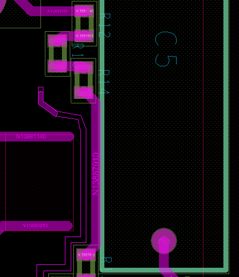
Im designing a high voltage circuit and I have a trace at a different potential than the capacitor it's running underneath.

My question has two parts, in general, what is the insulation around capacitors in general and is there a rule of thumb?

The second is in my particular case, I have 300VAC difference between my resistors and my trace running under my capacitor. The datasheet for the selected capacitor is here:https://www.mouser.co.uk/datasheet/2/212/KEM_F3033_PHE450-1104182.pdf

How do I find out whether is insulation is good enough?

enter image description here

\$\endgroup\$
1
  • \$\begingroup\$ It looks like you have a cut in the board just to the left of the trace. I assume you are following some type of clearance/creepage guidelines. I would say just keep following them with the capacitor too. Maybe mound the capacitor off the board and then goop it down for mechanical strength. \$\endgroup\$
    – vini_i
    Commented Apr 1, 2019 at 12:11

2 Answers 2

1
\$\begingroup\$

My question has two parts, in general, what is the insulation around capacitors in general and is there a rule of thumb?

There are 2 types of spacing that matter:

  1. electrical isolation, which ranges from functional insulation (which is required for a functional circuit (e.g. no flashover or tracking between conductors) to double insulation or reinforced insulation.
    There might be rules of thumbs, but better check the applicable standards (e.g. UL60950/EN60950 for standard power supplies).
    So, what isolation is required depends on what safety standard applies.
    Read for example this for a start about isolation.

  2. manufacturability The PCB manufacturer can tell best what spacing it likes best between components.
    Regarding your PCB, it is e.g. clear that wave soldering of R12 and R14 and others will become problematic because C5 is blocking the solder wave.

How do I find out whether is insulation is good enough?

According to provided datasheet, the Insulation Resistance Between Terminals and Case is ≥ 100 000 MΩ.
So, you don't need to worry about the case to trace for this capacitor. On your PCB, the isolation is measured from the right edge of the trace to the left edge of the round (through hole) pad.

\$\endgroup\$
2
  • \$\begingroup\$ The resistors are presumably topside (along with the cap in question) so they're either reflowed or wave soldered prior to insertion of the cap and wave soldering the underside. \$\endgroup\$
    – Phil G
    Commented Apr 1, 2019 at 18:59
  • \$\begingroup\$ @Phil Good point \$\endgroup\$
    – Huisman
    Commented Apr 1, 2019 at 19:02
0
\$\begingroup\$

You may get lots of displacement current induced into that trace, if the High Voltage is changing. To avoid this, the node must have low resistance; thus a precision voltage divider trace (the mid-point, the tap) should not be run under the HV cap.

This could lead to any regulator, any feedback loop, going into oscillation.

\$\endgroup\$

Your Answer

By clicking “Post Your Answer”, you agree to our terms of service and acknowledge you have read our privacy policy.

Not the answer you're looking for? Browse other questions tagged or ask your own question.