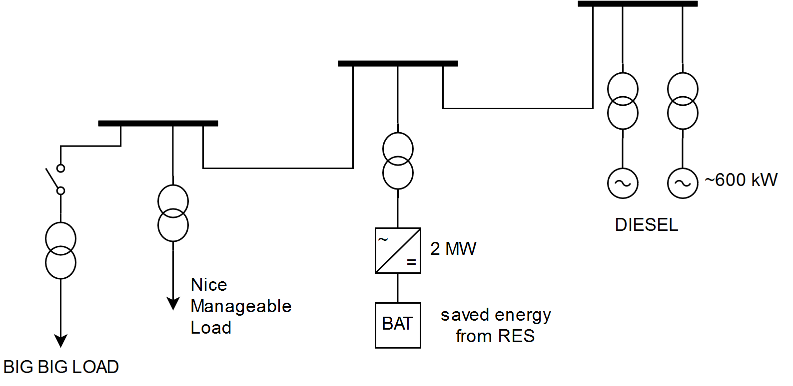
Ok, so after some time I have found some suggestions, based on several papers from IEEE and other sites. I will cite them in this post.
- Employ a larger (relatively to what the nominal power will be) T/F so that it does not go into deep saturation and draw a significantly lower inrush current. Obviously this increases the cost of the T/F. [1]
- Employ a VSI (Voltage Source Inverter) to moderate the voltage applied to the T/F. This kind of solution is known as Voltage Sag Compensators (or Voltage Dip Compensators). [1] [2]
- Sequential (not instant) closing of each phase of the switch that connects the T/F with the grid.In this way, dramatic reduction (or zeroing) of the inrush current is achieved, since each phase is connected at the appropriate time. Depending on the application, a residual magnetization measurement system may be required. The implementation also depends on the topology of the T/F (3 phase, 3x1 phase, Y / Δ). [3] [6]
- This method can also be combined with the placement of a resistance, from the common point of the windings to the earth, which during the transient phenomena is in series connected to the windings. [4] [5]
- Pre-magnetizing the iron core so that it does not need a large inrush current. This technique requires a system to measure the residual magnetization of the T/F since its previous deactivation. [7]
SOURCES:
[1] Po-Tai Cheng, Wei-Ting Chen, Yu-Hsing Chen, Chia-Long Ni, and Jarsun Lin, “A Transformer Inrush Mitigation Method for Series Voltage Sag Compensators”, IEEE TRANSACTIONS ON POWER ELECTRONICS, VOL. 22, NO. 5, SEPTEMBER 2007
[2] Yu-Hsing Chen, Chang-Yi Lin, Jhao-Ming Chen, and Po-Tai Cheng, “An Inrush Mitigation Technique of Load Transformers for the Series Voltage Sag Compensator”, IEEE TRANSACTIONS ON POWER ELECTRONICS, VOL. 25, NO. 8, AUGUST 2010
[3] Mukesh Nagpal, Terrence G. Martinich, Ali Moshref, Kip Morison, and P. Kundur, “Assessing and Limiting Im-pact of Transformer Inrush Current on Power Quality”, IEEE TRANSACTIONS ON POWER DELIVERY, VOL. 21, NO. 2, APRIL 2006
[4] Yu Cui, Sami G. Abdulsalam, Shiuming Chen, and Wilsun Xu, “A Sequential Phase Energization Technique for Transformer Inrush Current Reduction—Part I: Simulation and Experimental Results”, IEEE TRANSACTIONS ON POWER DELIVERY, VOL. 20, NO. 2, APRIL 2005
[5] Wilsun Xu, Sami G. Abdulsalam, Yu Cui, and Xian Liu, “A Sequential Phase Energization Technique for Trans-former Inrush Current Reduction—Part II: Theoretical Analysis and Design Guide”, IEEE TRANSACTIONS ON POWER DELIVERY, VOL. 20, NO. 2, APRIL 2005
[6] Yu-Hsing Chen, Ming-Yang Yeh, Po-Tai Cheng, Jen-Chuan Liao, and Wen-Yin Tsai, “An Inrush Current Reduc-tion Technique for Multiple Inverter-Fed Transformers”, IEEE TRANSACTIONS ON INDUSTRY APPLICATIONS, VOL. 50, NO. 1, JANUARY/FEBRUARY 2014
[7] Rickard Ekström, Senad Apelfröjd, and Mats Leijon, “Transformer Magnetizing Inrush Currents Using a Directly Coupled Voltage-Source Inverter”, Hindawi Publishing Corporation, ISRN Electronics, Volume 2013, Article ID 361643, 8 pages, http://dx.doi.org/10.1155/2013/361643
[8] KATSUJI SHINOHARA, KICHIRO YAMAMOTO, KENICHI IIMORI, YOSHITAKA MINARI,OSAMU SAKATA, and MICHIO MIYAKE, “Compensation for Magnetizing Inrush Currents in Transformers Using a PWM Inverter”, Electrical Engineering in Japan, Vol. 140, No. 2, 2002, Translated from Denki Gakkai Ronbunshi, Vol. 121-D, No. 7, July 2001, pp. 730–738
[9] Liana Cipcigan, Wilsun Xu, and Venkata Dinavahi, “A New Technique to Mitigate Inrush Current Caused by Transformer Energization”, 0-7803-7519-X/02/$17.00 © 2002 IEEE
[10] M. Syed Jamil Asghar, “ELIMINATION OF INRUSH CURRENT OF TRANSFORMERS AND DISTRIBUTION LINES”, 0-7803-2795-0
Hope it helps anyone with the same or familiar problem.

