For the choice of energy harvesting, I see you selected a series capacitor that is smaller the expected capacitance of the diode, so it's impedance only affects the Q of the current at resonance and depending on the choice of diode ought to be around 1 Ohm with sufficient energy and higher with less.
The load R effects resonance as well as the ESR of the load Cap which demands the use of smaller shunt caps with SRF>> 1GHZ.
Thus your series resonant L is simply 0.3nH as expected from 100pF and 915MHz which is far too low.
Consider the impedances of C1 L1 and C2 with 1 Ohm diodes for maximum power transfer. What do you get?
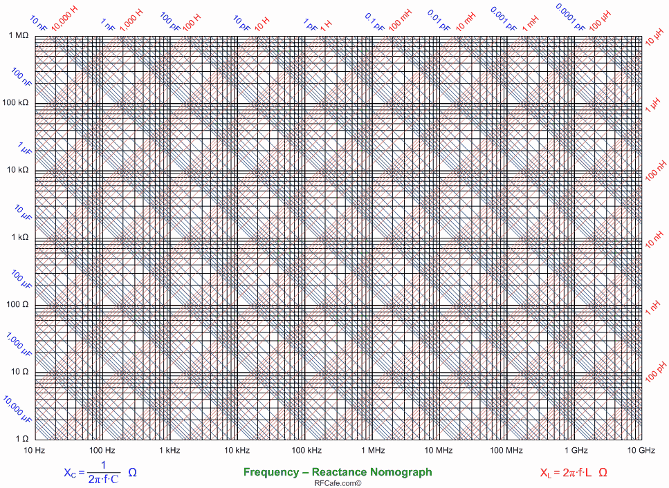
I use the RLC nomograph for a ballpark estimate, then Falstad tools to add ERS, ESL, and sliders. Then compare with Frequency response then update model to include more parasitics. But a Smith Chart with scattering parameters ( s values) from Murata would be best for low ESL with 1:2 L:W ratio on SMD.
Here is my result of 30 minutes of design time ( pro bono)
(free for what its worth)
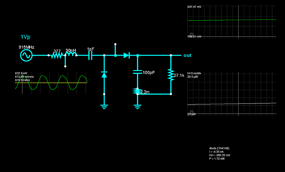
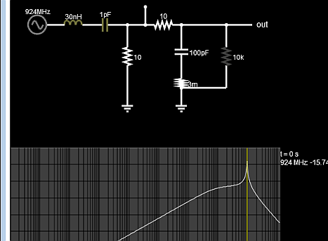 and another Sim link here
Your challenge is a design of an accurate stripline to mimic this circuit with a tradeoff for tolerance and selectivity given tolerances of dielectrics are 10% even with TDR testing on PCB maybe 5%.
Notice the Peak DC out matches the freespace Zo (377 Ohm source) peak voltage into R of 10 to 20k range.
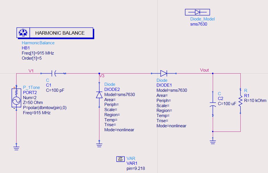
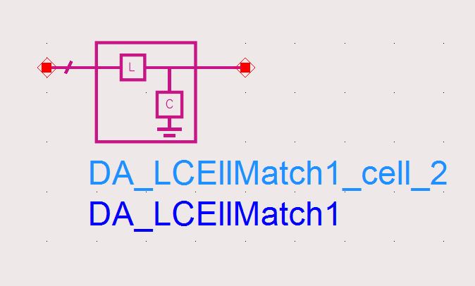
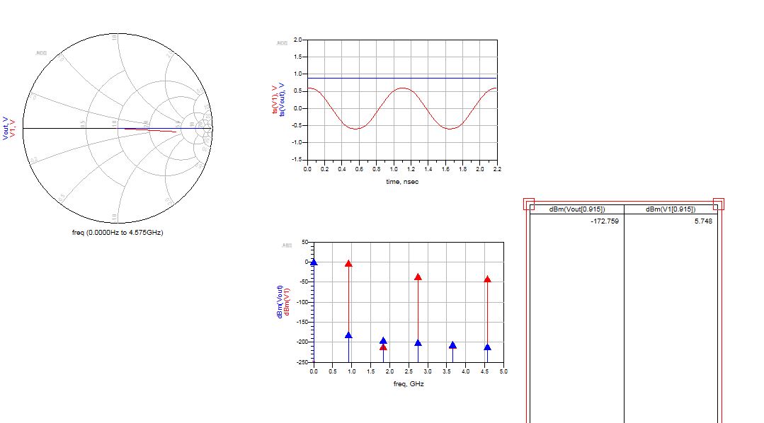 I am trying to use harmonic balance to find the impedance of the voltage double rectifier. After finding the impedance, I will use the impedance matching tool to find out the L matching.


