0
\$\begingroup\$

I made a generator for my wife's 3rd grade class, since they are learning about magnets, electromagnets and electricity. It's a simple pipe with a stack of magnets inside and you shake it to produce some power. I'm sure you've seen them.

The pipe (which is just a scrap plastic tube taken from one of my kids' "bubble wands") is about 1 inch diameter and the magnets are ceramic 3/4 inch ones from "Hobby Lobby". It's a sloppy fit, but it works. The coil is 26 gauge magnet wire and I made about 1,050 turns. At the ends of the coil, I soldered 2 LEDs with opposite polarity since it's AC and I wanted to show that. It all works, but I eventually want to go further with the project.

This leads me to my actual question. I discovered LTspice and want to replicate this in the simulation, but I have no idea how to setup the voltage source. I have been out of the electronics game for a long time and I think I'm missing something obvious. It requires a ground to simulate the circuit, but I have no idea where to put it. The more I try to do things with it, the more I don't know. Would any of you be able to show a quick way to setup this circuit, with the above information? Maybe even just estimate how much power I'm generating.

Thanks in advance.

\$\endgroup\$
2
  • \$\begingroup\$ What do you expect to see in your LTspice simulation? \$\endgroup\$ Commented Apr 11, 2019 at 15:43
  • \$\begingroup\$ Honestly, I don't know what I expect to see. I just was introduced to the software yesterday and I just wanted to do some looking around. I eventually want to add a rectifier circuit and maybe turn it into an emergency flashlight. I know how to setup a simple circuit with a battery but I just wanted to see what it would do with this as the power source. \$\endgroup\$
    – BigCountry
    Commented Apr 11, 2019 at 18:32

2 Answers 2

0
\$\begingroup\$

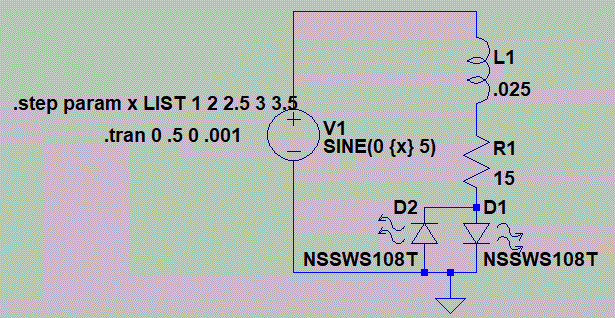
Am attacking a LTspice simulation, emphasizing simplicity.
Assumptions made:

  • The voltage generator amplitude is proportional to speed - shake faster gets you higher voltage. Simulation is 5 Hz (5 shakes each second).

  • Shaking generates a sinusoid voltage. Probably more like a triangle voltage, because this is not a rotating machine.

On to the coil. #26 wire is likely not optimum. Assuming an average coil diameter of 1.3 inches (it is no doubt a multilayer coil), with 1050 turns, resistance is in the 15 ohm ballpark. Better to use finer wire and get more turns: requires greater care in winding (fine wire tangles easily), and is more tedious without a winding machine.
Inductance of this coil might be 0.025 Henries - likely not a big factor unless you're a really fast shaker.

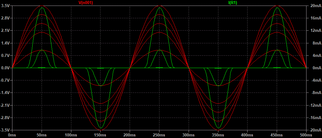
Be aware that LEDs give light proportional to current flow through them. So you really want to plot LED current vs. time in LTSpice transient simulation. But to get any current, the voltage generator has to exceed a LED's forward voltage of at least a volt or two. Slow shaking gets you no current, even though peak voltage is one volt. And choosing a RED LED may get you more light than a white LED, because RED LEDs start allowing current flow at a lower voltage (about 1.6V) than WHITE LEDs (about 2.5V) LTSpice has a few different LED models: try ones of different colour.
The big, white LED chosen here (NSSWS108) doesn't generate any light until the peak voltage rises above 2.5V:
LEDsim schematicenter image description here

\$\endgroup\$
1
  • \$\begingroup\$ This is great for simplicity and exactly what I was looking for. You're right I know my red led used has a forward voltage of 1.8 and the blue one I used has 3.2. This is exactly what I wanted to use lt spice for. I wanted a simple way to show the generator power supply, so I could then swap out different components in the rest of the circuit to see what it would do. Thank you. \$\endgroup\$
    – BigCountry
    Commented Apr 14, 2019 at 15:31
0
\$\begingroup\$

The easiest way to do this would be to make measurements of voltage and current from the coil and then present that to LT spice as an AC voltage source or a pulsed source.

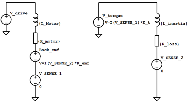
If you wanted more detail, you could run a motor simulation like this:

enter image description here Source: https://www.precisionmicrodrives.com/content/ab-025-using-spice-to-model-dc-motors/

The motor coil pictured above could be the calculated inductance of the shake coil, and the back emf could be the voltage generated from the magnet moving past the coil.

\$\endgroup\$
2
  • \$\begingroup\$ Let's say I just want to light an led. I get about 5v and about 300mA from the coil. The circuit would just be the coil to a resistor then the led and then back to the coil. What would that look like in spice? I'm not sure where to put the ground. Every time I make a circuit that loops like that, I get 0v. The ground is placed on the negative side of my voltage source. I also put 5v as my ac amplitude. I think I see what you're doing above though. I'll still tinker with that. \$\endgroup\$
    – BigCountry
    Commented Apr 11, 2019 at 18:41
  • 1
    \$\begingroup\$ Technically ground can be any point in the circuit, usually placed on the negative part of the supply. The ground is used in spice to provide a reference for the math, you need at least one ground. \$\endgroup\$
    – Voltage Spike
    Commented Apr 11, 2019 at 19:20

Your Answer

By clicking “Post Your Answer”, you agree to our terms of service and acknowledge you have read our privacy policy.

Not the answer you're looking for? Browse other questions tagged or ask your own question.