3
\$\begingroup\$

If there is only one SPI master and 8 SPI slave devices, How to we connect them together?

I am not allowed to have 8 dedicated Slave select pins on the master, nor am i allowed to daisy chain the complete setup

I was asked this question in an interview and i am not able to figure it out.

\$\endgroup\$
6
  • \$\begingroup\$ What about a MUX for the CS lines? How many Chip Select lines are you allowed? \$\endgroup\$
    – Puffafish
    Commented Apr 16, 2019 at 9:12
  • \$\begingroup\$ I am not sure how many are allowed,the Mux is a good idea,but i think the idea is to reduce the chip select pins if we are using a MCU with a low pin count.Can this be done in software?? bit banging.. \$\endgroup\$
    – AK47
    Commented Apr 16, 2019 at 9:15
  • \$\begingroup\$ So you use 4 pins out of the MCU into a MUX to give you your 8 chip select lines. Hence reducing the chip select lines out of the master MCU. \$\endgroup\$
    – Puffafish
    Commented Apr 16, 2019 at 9:18
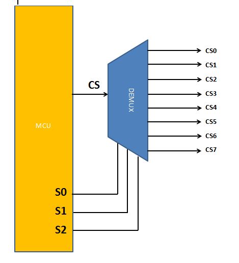
  • \$\begingroup\$ CS pin will go to a 1x8 demux. Select lines will be 3 digital pins of MCU. \$\endgroup\$
    – Mitu Raj
    Commented Apr 16, 2019 at 9:31
  • 1
    \$\begingroup\$ @Mitu Raj: If its not too much trouble could you draw me a basic block diagram of it.It would be very help full. \$\endgroup\$
    – AK47
    Commented Apr 17, 2019 at 4:53

2 Answers 2

3
\$\begingroup\$

To reduce pin count, the normal way would be to use a demultiplexer that take 3 pin binary code and gives out 8 pin individual signals. Such as 74HC251.

That is, you can't use any "automatic /SS" features of SPI but must handle /SS manually by setting 3 pins. Optionally use a 4th pin to the /CS of the demux if you want to shut off all communication with no slave selected.

MOSI, MISO and clock are all connected to all nodes with no logic in between.

\$\endgroup\$
4
  • 1
    \$\begingroup\$ Without having any sources for the claim, I'd say this is the most common way to deal with multi-slave SPI. It seems far more common than daisy chain. \$\endgroup\$
    – Lundin
    Commented Apr 16, 2019 at 9:38
  • \$\begingroup\$ Could you draw me a basic block diagram.it would be very helpful in understanding the pin connections \$\endgroup\$
    – AK47
    Commented Apr 17, 2019 at 4:55
  • \$\begingroup\$ @ArunKumar Read the 74HC251 datasheet and take it from there. There's only one way to use it so it should be mostly self explanatory. \$\endgroup\$
    – Lundin
    Commented Apr 17, 2019 at 6:49
  • \$\begingroup\$ Thanks i understood it perfectly.so the 3 inputs S0,S1 and S2 go to the MCU and act as CS combinations(2^3=8 combinations). And the outputs I0 to I7 will go to the 8 slaves. \$\endgroup\$
    – AK47
    Commented Apr 17, 2019 at 8:59
2
\$\begingroup\$

enter image description here

This is the idea, that we were talking about. De-muxing the CS pin using 3 control pins from the MCU, so that only one slave will be selected at a time. It just saves four pins. MOSI, MISO and CLK pins will however be common. A simple 1x8 demux example: 74hc138

\$\endgroup\$
0

Your Answer

By clicking “Post Your Answer”, you agree to our terms of service and acknowledge you have read our privacy policy.

Not the answer you're looking for? Browse other questions tagged or ask your own question.