0
\$\begingroup\$

I have a couple of china-cheapie devices that seem to use some circuit with a single button where first push turns it on, second turns it off -- e.g. the button works as a toggle.

I would prefer to control these devices from an embedded device such as an arduino or a raspberry pi.

For example, one came with a small sample of smart-tint pdlc material that I would like to use as switchable frosted-glass on a small project:

PDLC smart tint inverter

smart tint glass sample ebay

EDIT begin: picture of the internals added. 3V smart-glass driver
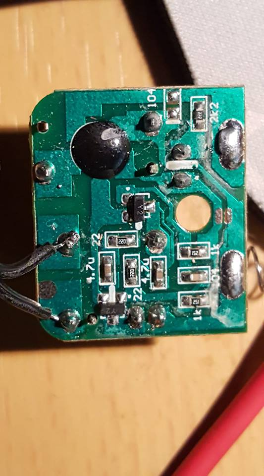
Not a lot in this thing. And there wasn't a lot to see from the top. The area around the black circle is the temporary push button switch. The pins on the bottom left are the secondary (AC output) of a small transformer - you can see the primary pins of the transformer on either side of the 4.7u cap in the bottom middle. Power in is on the left from two AA batteries (spring is -) Indicator LED in the top right. (the switch, xfmr and led are all that stick out the other side that I can see - one sided PCB) I'm guessing the two Y2 SMD are SS8550 PNP transistors. (google searches)

But after discovering they aren't very power tolerant (I let the magic smoke out of one of them) I'm now wondering if I shouldn't try to chase down a 5vdc to ac converter (this one seems to put out about 7vac at 500Hz, but another that came with a AC converter does 17vac at 60Hz)

I'd still be curious how to find and side-step the flip-flop part of the circuit though as I have other stuff like these that would be fun to power and switch digitally.

---Edit end---

Another is a 5v mist maker (ultrasonic piezo vaporizor). I have an alternate solution (Seeed makes a grove based one for this) but would still love to know if there's any easy way to replace their switching methods.

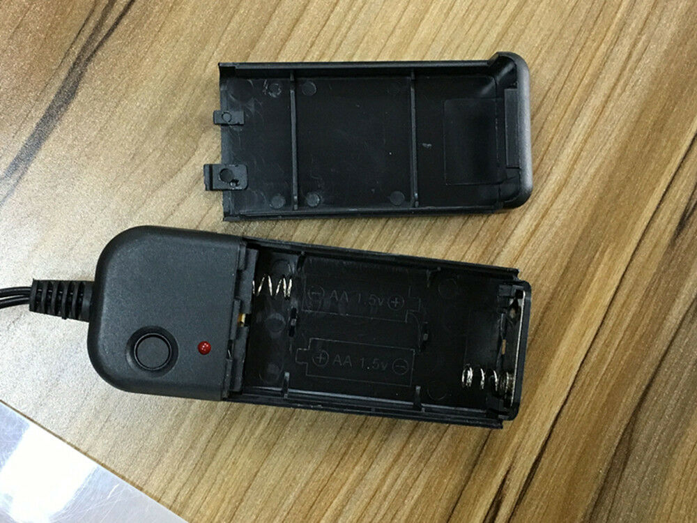
5v Mist Maker

\$\endgroup\$
5
  • \$\begingroup\$ Depends on the way the switch works. Is the switch a momentary switch (which triggers some kind of micro controller) or is it latching? What current is the switch activating? What voltages have you got there? \$\endgroup\$
    – Puffafish
    Commented Apr 16, 2019 at 15:31
  • \$\begingroup\$ What is your question? If you get out a voltmeter and observe the behavior of the switch terminals in relation to the behavior of the device, you should be be able to replicate that behavior with an Arduino that shares a common reference voltage/ground. \$\endgroup\$
    – Bort
    Commented Apr 16, 2019 at 15:32
  • \$\begingroup\$ What are your questions? How to switch 60Vac low power and How to switch 5V low power ? with an Arduino? or how to tell replace a push-push interface with an On/Off interface? It's all in the interface specs. Push push is just a toggle flip flop that can be bypassed. \$\endgroup\$
    – D.A.S.
    Commented Apr 16, 2019 at 15:41
  • \$\begingroup\$ Yeah, I'm trying to bypass the flip-flop. But I'm new to digital logic circuits (I haven't done them since college 30 years ago). Not sure what to look for. I'll post pics of the internals. \$\endgroup\$
    – Scott Wood
    Commented Apr 17, 2019 at 2:32
  • \$\begingroup\$ I'm guessing (limited experience here) that the flip-flop probably ends somewhere after the first transistor? Something on there has to be creating an oscillation for the AC. \$\endgroup\$
    – Scott Wood
    Commented Apr 17, 2019 at 2:41

2 Answers 2

3
\$\begingroup\$

Simple momentary push buttons can be made dirt cheap in quantity. Push-push switches, definitely not. The cost ratio between a momentary switch plus a bit of electronics*, vs. a mechanical push-push switch, is huge. As a bonus, a momentary plus electronics is cheaper to make reliable.

So on a cheap consumer product, the on/off switch is almost certainly implemented by a momentary switch plus some circuitry. For any given product, you'll have to do a visual inspection, plus maybe some poking around with a multimeter.

* And if the product has a microcontroller in it, that "bit of electronics" can easily be the microcontroller itself.

\$\endgroup\$
0
\$\begingroup\$

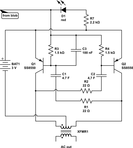
it looks like a two transistor astable multivibrator driving that transformer push-pull

the wire that lights the LED also supplies base current for the transistors so it acts to turn the inverter on and off

schematic

simulate this circuit – Schematic created using CircuitLab

Cut the track the runs from the black blob past the unsoldered switch pin to the LED.

putting 0V (the spring terminal) on this track will turn inverter that produces the AC on. (you could solder a wire to the LED pin)

\$\endgroup\$
2
  • \$\begingroup\$ thanks, I'll see if I can translate to the piece tonight on one of them and give it a shot! \$\endgroup\$
    – Scott Wood
    Commented Apr 17, 2019 at 17:30
  • 1
    \$\begingroup\$ that transformer is probably just too small, to get a higher voltage out of it they have increased the frequency but now the frequency is too high to drive the film well. if you can replace it with a 110 to 12-0-12 transformer and drive that from 5V at 50 hz using a similar circuit you'll proably get better results. \$\endgroup\$ Commented Apr 17, 2019 at 20:36

Your Answer

By clicking “Post Your Answer”, you agree to our terms of service and acknowledge you have read our privacy policy.

Not the answer you're looking for? Browse other questions tagged or ask your own question.