0
\$\begingroup\$

enter image description here

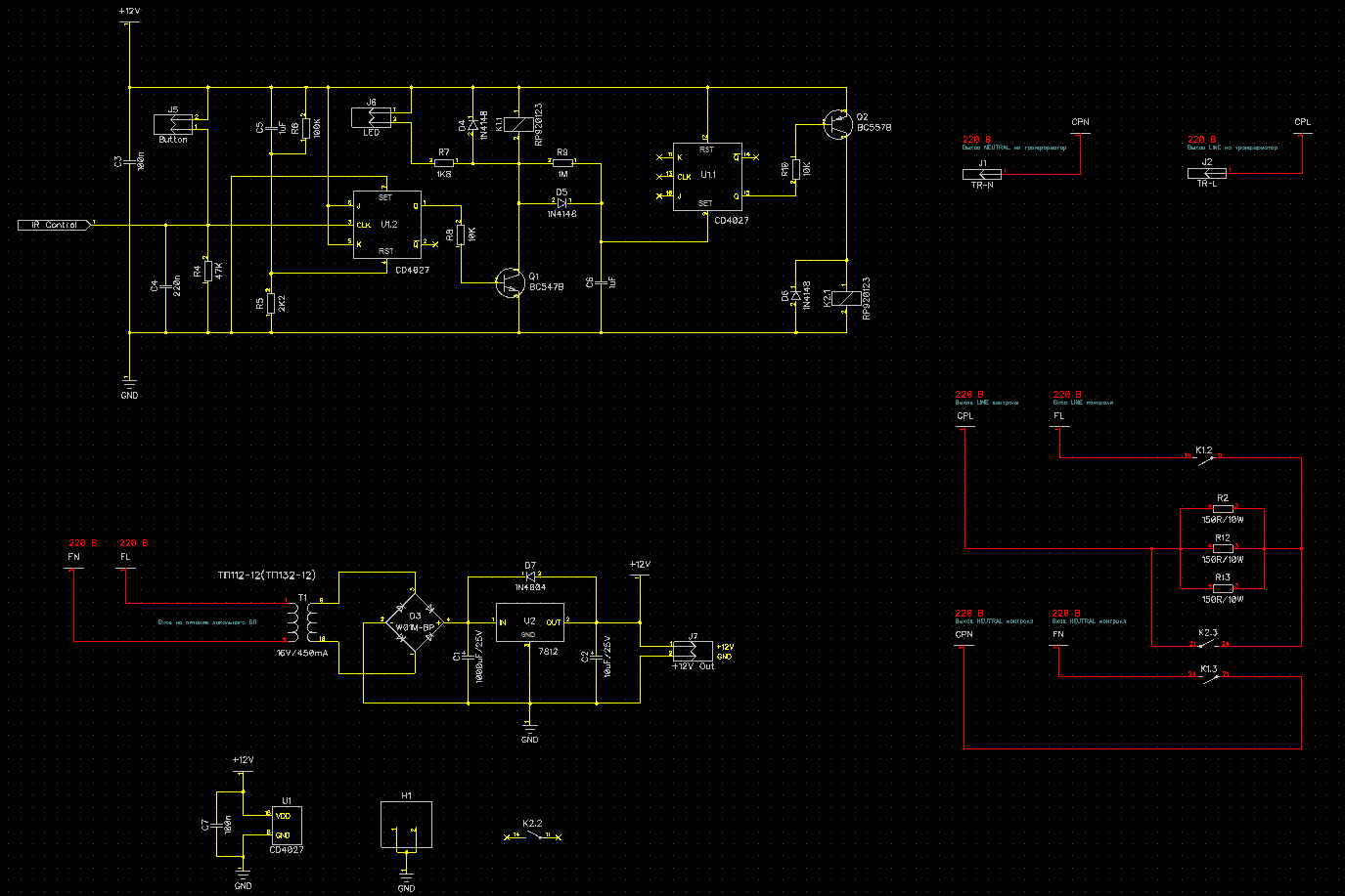
I have this simple surge protector and soft start inside the PSU. My transformer is out of its specifications yields 21.3V after bridge rectification. And 0.1A load (12V fan for cooling pass transistor) makes the 7812 very hot (despite it has a heatsink). So i decided to replace the 7812 with R-78E12-0.5 as it is a pin-2-pin replacement to 78xx. But after i did it, the CD4027 started to do weird things... after I push the On/Off tactile switch the National Semiconductor 4027 always switch the relays ON and TI CD4027 always OFF. I have desoldered the R-78E12-0.5 out and put the 7812 back - and the circuit is working as it should be...

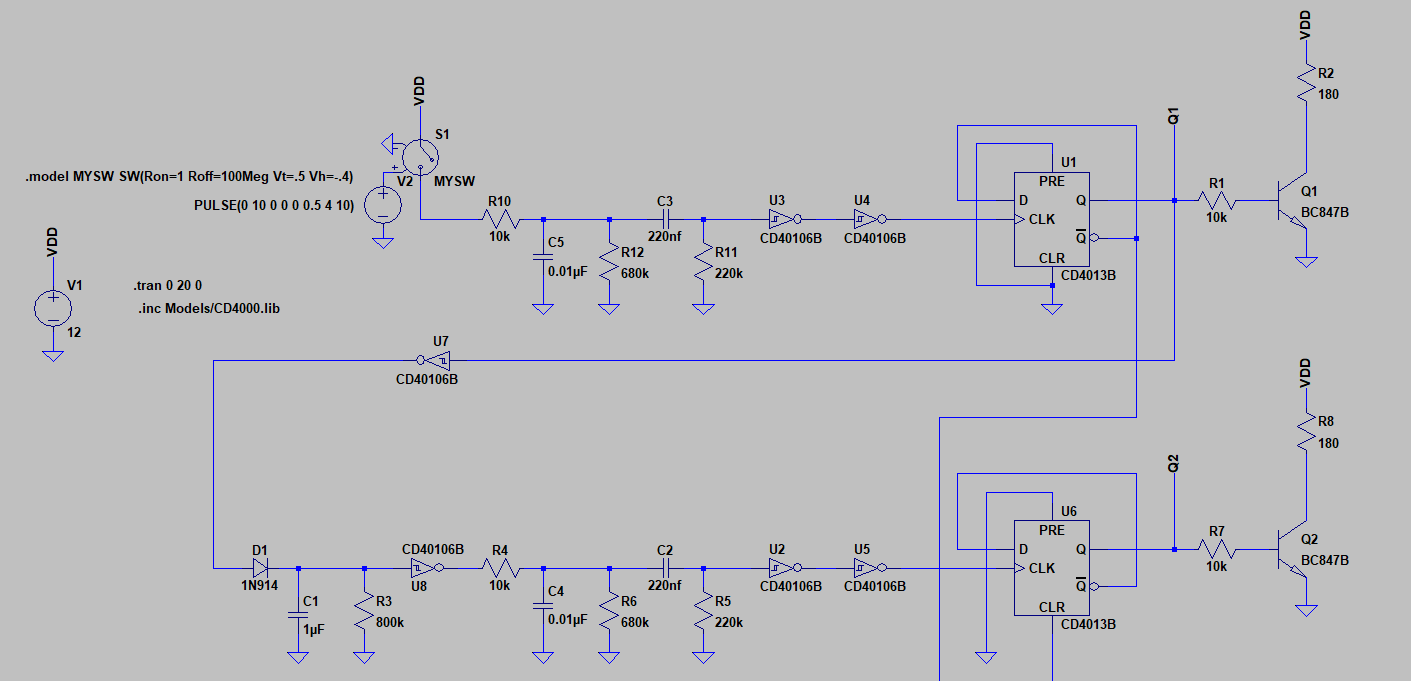
UPDATE: After the answers of user287001 and Huisman I have completely reworked the Soft Start. The simulation worked. Will try it on breadboard in couple of days.

enter image description here

\$\endgroup\$
0

2 Answers 2

1
\$\begingroup\$

You have a capacitor in the clock pulse wire of 4027. That makes clock pulses slow. There's plenty of time when very small amount of noise can cause unpredictable behaviour. You have a perfect noise generator: The switcher in place of 7812. There's another even weaker point: the undefined inputs of the 2nd 4027. Unconnected CMOS inputs easily catch available noises in the air. If they really are unconnected, you have been lucky until this.

Unfortunately we do not know your wiring. Typically people go where the fence is the lowest if they do not think what pulse circuits demand. Thus there can be more. Add some photos, someone here can be able to see something.

You should have no logic signals which are slowed down with capacitors. All logic signals should be 0 or 1 with as fast transient between the states that the logic family itself usually produces. You should have Schmitt triggers to interpret the slow signals and make exact zeros and ones.

\$\endgroup\$
0
\$\begingroup\$

Maybe you should at least draw the minimum load 2% load for the R-78E-12-0.5 to be stable for your circuit. This means 0.5A * 2% = 10 mA.
The CD4027 draws uA, so it hardly contributes. And further loads are the 100k\$ \Omega\$ plus 2.2k\$ \Omega\$ .

Do place a 1.2 k\$ \Omega\$ between the output and the ground of the R-78E-12-0.5 and check whether that helps.

\$\endgroup\$
1
  • \$\begingroup\$ Unfortunately, no luck! \$\endgroup\$
    – Roman
    Commented Apr 19, 2019 at 23:59

Your Answer

By clicking “Post Your Answer”, you agree to our terms of service and acknowledge you have read our privacy policy.

Not the answer you're looking for? Browse other questions tagged or ask your own question.