0
\$\begingroup\$

The problem that I have is that I can't understand the working of PWM in Arduino, even though I totally understand what PWM is.

Like the Arduino has a 980hz refresh rate (~1ms clock speed) on two of its PWM pins and 490hz refresh rate (~2ms clock speed) on the others PWM pins.

Then there is Arduino's internal crystal oscillator which works at 16Mhz (~62ns clock speed).

And then I came across this answer:

Why change microcontroller's PWM frequency?

In this the accepted answer gives a little overview on how PWM works.

But I can't seem to understand how does PWM wave fits inside the input window of PWM pins.

As PWM pin take input in every ~1-2ms how are PWM waves formed inside that input window? Can someone explain by showing an example of working like the above answer did.

And does the clock speed of crystal oscillator have anything to do in this process?

*I am totally new to electronics

\$\endgroup\$

3 Answers 3

2
\$\begingroup\$

You might find the AVR131: Using the AVR’s High-speed PWM application note useful.
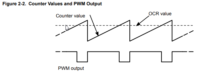
enter image description here

Let's be clear on a couple of points regarding PWM.

  1. A fixed frequency pulse train is generated.
  2. The pulse-width is modulated (adjusted) so that the on-time varies from 0% to 100% depending on the "analog" value fed to the PWM register.

Let's say you want a PWM with a resolution of 256 steps.

  • The PWM counter is reset (to zero) at the start of each PWM cycle and the output is switched high.
  • A counter starts counting at a rate determined by the PWM oscillator and configuration registers. This count value generates the ramp shown in Figure 2-2.
  • When the counter exceeds the OCR threshold value the output is switched off (but the counter keeps on going to 256).
  • On the clock pulse after 255 the counter rolls over to zero, it resets and the process starts again.

It should be clear by now that the maximum possible PWM frequency would, in this case, be CPU clock / 256 but it may be much lower due to other divisions, etc., in the PWM controller.

So, to answer your questions:

But I can't seem to understand how does PWM wave fit inside the input window of PWM pins.

The beauty of PWM is that the output is either fully on (high or 1) or fully off (low or 0). This makes it very easy to implement with digital logic. There is no waveform inside - only binary counters and binary comparators. It is the average value of the output that gives the analog output.

This can work digitally to, for example, dim the backlight in your phone. The backlight is switched between fully on and fully off quickly enough that you don't notice the flicker and the brightness appears to be proportional to the PWM duty cycle. For a true analog signal - a voltage varying between 0 and 5 V, for example, then a simple RC (resistor-capacitor) low-pass filter may suffice.

As PWM pin's take input in every ~1-2ms how are PWM waves formed inside that input window?

Hopefully that's clearer now.

And Does the clock speed of crystal oscillator has anything to do in this process?

Yes. Everything will be based on that but usually after having been divided down by some power of 2 (4, 8, 16, etc.).

\$\endgroup\$
6
  • 1
    \$\begingroup\$ The frequency doesn't necessarily have to be an even power of two division. You typically set a 16 bit counter value to set the cycle length in (divided) clocks, and then a second 16 bit counter to a lower value to set the duty cycle. The timer sets the output low, then starts counting down from the counter register value to zero, and as it passes the duty cycle value it switches the output high. \$\endgroup\$
    – nsayer
    Commented Apr 19, 2019 at 16:29
  • \$\begingroup\$ @nsayer There are several different modes, what you just said is one of them, what transistor said is another one. \$\endgroup\$ Commented Apr 19, 2019 at 16:42
  • \$\begingroup\$ On layman's terms, the 1-2ms input windows has 256 steps in it (1ms/256 = 1 step) and each step has a repetitive process in it. But how much duration is one step of approx.? And as the cpu speed is capable of performing this operation at a much higher speed then why doesn't it do so? \$\endgroup\$
    – Vasu Deo.S
    Commented Apr 19, 2019 at 16:48
  • \$\begingroup\$ Have you read the linked article yet? It may take a couple of reads before understanding dawns. \$\endgroup\$
    – Transistor
    Commented Apr 19, 2019 at 16:53
  • \$\begingroup\$ can you please tell me the exact page in the article which i should read. As the article is way too advance as per my level, and there is way more stuff in it then what i am familiar of!!! Sorry,I am a noobie in electronics, so a little weak on these topics \$\endgroup\$
    – Vasu Deo.S
    Commented Apr 19, 2019 at 17:07
2
\$\begingroup\$

As I read the question, I see repeated reference to "input window of a PWM pin." I may be misunderstanding that, but it makes me think that you may be thinking of PWM pins as inputs. They're not - they're outputs. They output a square wave of a varying duty cycle. You can turn that into analog by adding an RC low-pass filter.

You also talk about forming PWM waves inside of the input window. My reading of that suggests that you may be trying to make a complex waveform where the waveform changes more frequently than the PWM frequency. This is not possible. PWM output can be used to make a complex waveform, but the rate of change of that output is going to be limited by the low-pass filter that converts the PWM output into analog, and that's going to be related to the PWM frequency, which will also limit the granularity of the duty cycle.

If you want to make high speed complex analog waveforms, then you have no choice but to use a proper DAC instead. PWM outputs converted to analog can only really be used to create analog voltages that change very slowly.

\$\endgroup\$
3
  • \$\begingroup\$ so PWM Pins are only capable of analog outputs? Is there any way of getting analog inputs? \$\endgroup\$
    – Vasu Deo.S
    Commented Apr 19, 2019 at 16:49
  • 1
    \$\begingroup\$ Yes. Use the analog input pin! \$\endgroup\$
    – Transistor
    Commented Apr 19, 2019 at 16:54
  • \$\begingroup\$ @Transistor is correct - if you want analog input, you should use the ADC to read an analog pin. Also, strictly speaking PWM pins are not capable of analog output - they make variable duty cycle square waves. But those can be converted to analog with an RC filter. \$\endgroup\$
    – nsayer
    Commented Apr 20, 2019 at 17:28
1
\$\begingroup\$

You might want to take a look at timer section of the the datasheet of the microcontroller you have on your Arduino, it will explain how it works. But basically, if you have a 8-bit timer, there are 256 steps before it overflows. The timer will run on the crystal frequency, or some division of it, and will set the PWM output pin high when counter matches 0, and will set the PWM output pin low when counter matches user set value.

\$\endgroup\$

Your Answer

By clicking “Post Your Answer”, you agree to our terms of service and acknowledge you have read our privacy policy.

Not the answer you're looking for? Browse other questions tagged or ask your own question.