3
\$\begingroup\$

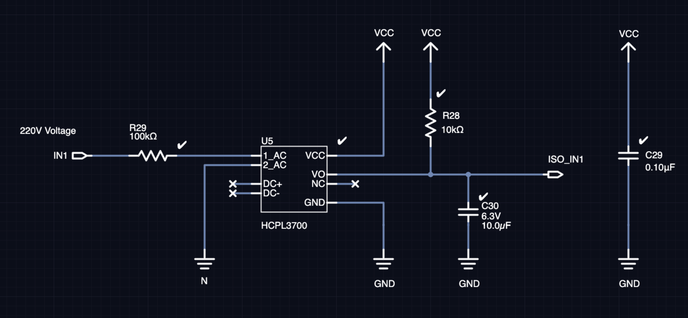
I want to use HCPL3700 optocoupler for sensing 220V (line). I design a circuit but I want to ask some questions.

  • HCPL3700 is an open-collector output so I pull-up Vout. In AC voltage sensing some people says HCPL3700 is halted on zero-cross so I add a cap (C30) is this (10uF) enough for zero-cross pulse filtering?

  • I add a resistor (R29) (100k) to the input of HCPL3700 for 200V threshold is this ok?

thanks

enter image description here

\$\endgroup\$
3
  • \$\begingroup\$ R29 is unlikely to have a voltage rating of the peak of your mains voltage, \$ 220 \sqrt 2 \$. It should be made up of two or more series resistors. \$\endgroup\$
    – Transistor
    Commented Apr 22, 2019 at 15:41
  • \$\begingroup\$ C30 will not work. When in pull-up it will charge the 10uF cap slowly via R28, a 10k resistor. When in pull down it will pull down almost instantaneously, shorting any voltage on the capacitor. Destructive. I think you need a 100k series resistor before C30 to fix both problems. \$\endgroup\$
    – scorpdaddy
    Commented Apr 22, 2019 at 18:06
  • \$\begingroup\$ Did you build it? I'm trying with 2*47k resistors and with a cap 22 uF in the DC+- \$\endgroup\$ Commented Sep 13, 2021 at 22:27

2 Answers 2

1
\$\begingroup\$

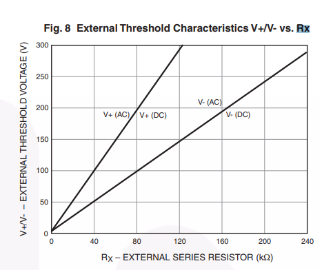
Yes, not only is R29 OK, I think it might be mandatory. Take a look at the graph below from the data sheet. It indicates that the value of the series resistor affects the detector's switching threshold. It's hard to tell from the graph which curve to use. Suggest you use the 100K and then measure the voltage where the detector changes state. Tune the value of R29 until you're happy with the voltage threshold.

Fig. 8 External Threshold Characteristics graph from HCPL3700 datasheet

(Image source: Figure 8 from HCPL3700 datasheet)

\$\endgroup\$
6
  • 1
    \$\begingroup\$ The answer should also address the asymmetric pull up/down and the effect on C30 and the signal ISO_INT. \$\endgroup\$
    – scorpdaddy
    Commented Apr 22, 2019 at 18:07
  • \$\begingroup\$ @scorpdaddy do you know if the C30 is ok? also, why there is no capacitor in DC+ and DC- pins on the chip? \$\endgroup\$ Commented Sep 3, 2021 at 19:34
  • \$\begingroup\$ @CarlosGarcia, C30 is not ok for two reasons. 1) The RC time constant of R28+C30 is around 100ms, which will limit a signal with a whole wave period of 17ms. 2) There needs to be a series resistor between U5 and C30 to limit the current on U5:VO when it tries to pull the charge out of C30. \$\endgroup\$
    – scorpdaddy
    Commented Sep 13, 2021 at 18:46
  • \$\begingroup\$ @scorpdaddy Thanks a lot! I'm still trying to figure out why those caps, and not one between DC+ and DC- \$\endgroup\$ Commented Sep 13, 2021 at 22:28
  • \$\begingroup\$ @CarlosGarcia sometimes the bypass caps from DC+ to DC- are left out in the forums to simplify the circuit in discussion. But in general, it is better to post ones whole circuit. You would certainly have one or more bypass caps in the real circuit. If you want to learn more about bypass capacitors I suggest searching the forum rather than raising the question in the comments section of a different question. \$\endgroup\$
    – scorpdaddy
    Commented Sep 14, 2021 at 23:55
0
\$\begingroup\$

This question has already been answered here: How to sense AC with a 5V Microcontroller

\$\endgroup\$

Your Answer

By clicking “Post Your Answer”, you agree to our terms of service and acknowledge you have read our privacy policy.

Not the answer you're looking for? Browse other questions tagged or ask your own question.