3
\$\begingroup\$

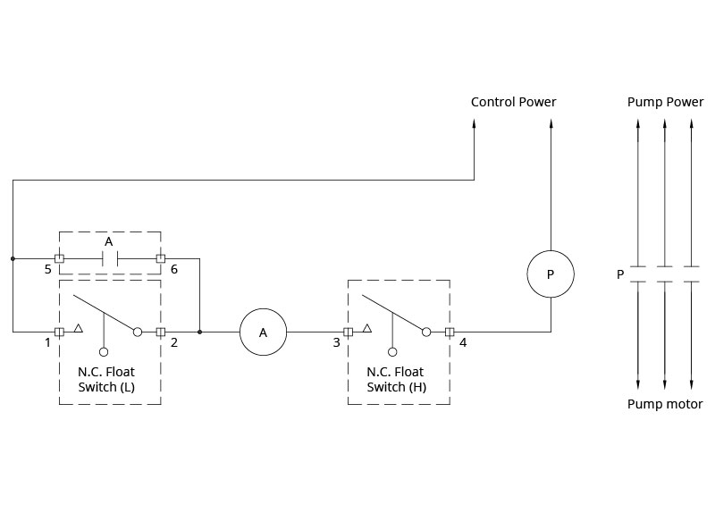
I'm trying to build a hysteresis water pump system with 2 water level switches. Please see the diagram and explanation of this setup I've taken off the web:

Diagram of hysteresis water pump system

The first switch (L) is set at the minimum liquid level desired in the tank. The second switch (H) goes at the maximum desired level. When the liquid is below both switches, they are both closed; the pump runs, filling the tank. As the liquid fills past the first switch, it opens. However, seal-in relay A has been activated and closed, bypassing the now-open switch L (effectively “sealing it in”), so the pump continues to run until the high-level switch H opens. When the high-level switch opens, the motor relay P opens, stopping the motor, and seal-in relay A opens.

My question is, what is a seal-in relay in the consumer market?

I can buy water level switches on ebay for like 5 bucks, but I am finding it hard to find what a seal-in Relay switch is that is needed for this schematic. And i'm looking at something very basic and cheap to be just enough to do the task. My problem is I can't buy this item because searching for seal-in relay gets me no where.

Thanks!

\$\endgroup\$
0

2 Answers 2

4
\$\begingroup\$

A "seal in" contact is just another normally open contact on a relay.

The name "seal in" comes from the application of the contact. Most electronics people aren't likely to have heard of the terminology of "seal in". The term is used in industrial controls (which now days use relays and PLC).

Choose a relay that is suitable for your needs.

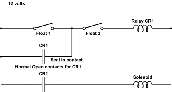
Edit 1 : Obtain a relay that has 2 contacts. Use your level switch to turn on the relay. Use one of the relay normally open contacts to drive your pump motor. Use the relay's 2nd normally open contact as your "seal in" contact, which is then wired across your level switch.

So, use your level switches to drive relays which can handle higher current than your level switches. Then the relay contacts are used where you would normally place your switches.

EDIT 2 : To search for a relay, use the words "control relay". A control relay contact can be called a "seal in" or any other name you desire.

schematic

simulate this circuit – Schematic created using CircuitLab

Here is a circuit that should work for you.

You can use 12 volts or 24 volts. Just get relay with coil voltage to match what you want to use.

\$\endgroup\$
4
  • \$\begingroup\$ Sorry, can you expand a bit? I have very little electrical background. So I was told that for each water level switch, I will need a relay, because the switches them selves can't pass so much current that is needed for the motor to run.. so they will pass a bit of current to the switch, and the rest will flow through the relay... So are you suggesting, this basic 4 wire relay that comes with a water level switch will be able to SEAL in my connection on the LOW water switch? \$\endgroup\$
    – ebeygin
    Commented May 1, 2019 at 18:16
  • \$\begingroup\$ @ebeygin I edited my answer to include more info. \$\endgroup\$
    – Marla
    Commented May 1, 2019 at 18:20
  • \$\begingroup\$ Are you using a 3 phase pump as shown in your wiring diagram ? \$\endgroup\$
    – Marla
    Commented May 1, 2019 at 19:01
  • \$\begingroup\$ My pump is a basic fountain 12v pump with positive and negative terminals. The pump is not needed in this circuit, in my use case, its always on to circulate water through the tank, but the switches are for a water solenoid valve (and that runs on 24VAC). When there is little water in the tank, I want to fill it up to the top. The switches will control when I fill the tank. My switches are basic switches with two wires.. i have no relays yet.. but i'm trying to build a system with two switches, one for sense FULL and one for sense low water (to know when to turn on water solenoid valve).. \$\endgroup\$
    – ebeygin
    Commented May 1, 2019 at 20:04
2
\$\begingroup\$

Some relays are provided with a holding mechanism comprising a small coil in series with the contacts; this coil is on a small electromagnet that acts on a small armature on the moving contact assembly to hold the contacts tightly closed once they have established the flow of trip-coil current.

This coil is called a "seal-in" or "holding" coil.

It can be interrupted only by an auxiliary switch that is connected in series with the trip-coil circuit and that opens when the breaker opens.

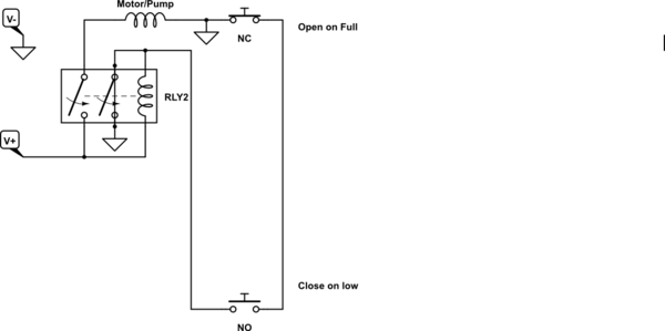
Alternate methods as @Marla described depends on how the coil and motor are switched sharing the same voltage. e.g. DC high-side or low-side using V+ or 0V with a normally open contact so that the relay contact also shunts the low sensor switch so the relay stays latched. e.g. as shown below.

schematic

simulate this circuit – Schematic created using CircuitLab

This is a conceptual DC example, and there are other ways to do this for DC and AC.

\$\endgroup\$

Your Answer

By clicking “Post Your Answer”, you agree to our terms of service and acknowledge you have read our privacy policy.

Not the answer you're looking for? Browse other questions tagged or ask your own question.