1
\$\begingroup\$

I'm currently doing a project that requires the charging of a 2s Li-Ion battery.

I have an 18V 10W solar panel that I want to charge my battery using a buck converter. Im controlling the switch and duty cycle with an arduino uno which outputs a 0-5V PWM signal, I have not selected a switch yet as I am having issues trying to get my mosfet switch on and off due to the gate voltage being significantly less than my source voltage.

The way I understand it,

Before the switch the voltage is 18V, after the switch before the inductor the voltage at that node is the same as the battery voltage, 7.2< Vbat <8.2V. Therefore, for mt arduino uno to drive the switch some sort of DC offset needs to be applied to the gate so it varies from below the battery voltage (switch OFF) to above the battery voltage and turn on voltage of the switch ( switch ON).

Is my understanding correct? Does anyone have any suggestions how I can drive my switch without losing too much power?

Basically im struggling to get a PWM signal of 0V - 18V after the switch.

IN CC mode my desired outputs are 1Amp and varying voltage and in CV mode Vout = 8.4V and slowly decreasing current.

Is there some kind of IC driver that I can use?

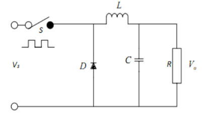
BUCK CONVERTER from https://www.researchgate.net/publication/291757375_Design_and_Simulation_of_DC-DC_Converters

\$\endgroup\$

2 Answers 2

1
\$\begingroup\$

Two general things:

  1. Do not drive the MOSFET directly from your MCU. Well that actually depends .on your switching frequency. But if you want to quickly switch on and off your FET to reduce switching losses, you need to source and sink a lot of current .

Also your MCU voltage is limited but you want to overdrive the MOSFET to switch on faster and reduce Rdson.

You don’t want ask or expect the MCU to do this.

  1. You need to drive the Gate at least 7-10V depending on FET higher than the source. A common way to do this is bootstrapping.

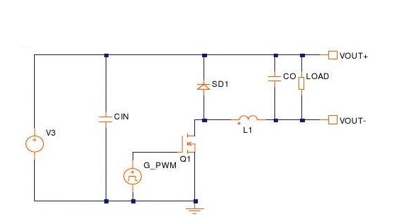
Alternatively , you can float your battery/output. And reference the FET to ground this will make driving the gate easier. This is commonly done in LED drivers. See figure below.

enter image description here

picture take from Here

\$\endgroup\$
2
  • \$\begingroup\$ I am using a switching frequency of 20kHz. Cool, thank you for the help! I'll do some research on bootstrapping :) \$\endgroup\$
    – Zee96
    Commented May 3, 2019 at 8:42
  • 1
    \$\begingroup\$ Using the MOSFET on the low side is definitely the easiest way of doing this. At 1A however, a SOT23 MOSFET would probably work just fine. They generally have a low enough gate charge that any microcontroller can drive it easily. To monitor the voltage across the battery, it is probably easier to use two voltage dividers and measure the voltage across of the solar panel and the negative of the battery relative to GND and do the subtraction on the microcontroller \$\endgroup\$
    – c10yas
    Commented May 3, 2019 at 8:42
1
\$\begingroup\$

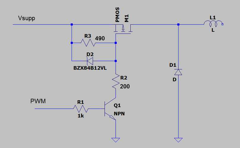
Use P-channel Mosfet (better solution for high-side switch) - no need higher voltage than Vsupp.

Edit:

Something like this:

enter image description here

Vsupp = 18V PWM = 0-5V

Edit:

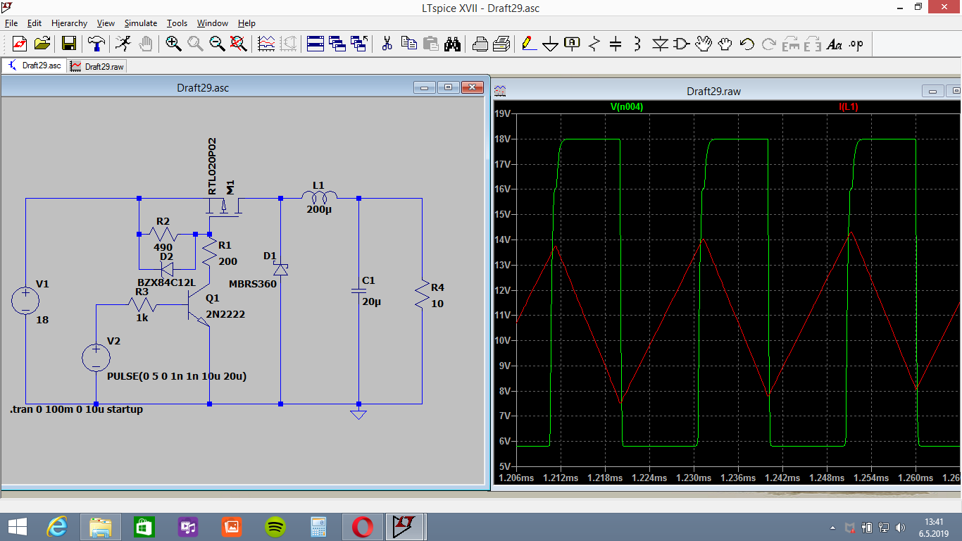
LTspice simulation of buck (green is Gate voltage):

enter image description here

\$\endgroup\$
5
  • \$\begingroup\$ Unfortunately when I tried the same in LTspice I did not get what I was looking for, did it work when you ran it? \$\endgroup\$
    – Zee96
    Commented May 6, 2019 at 9:30
  • \$\begingroup\$ I had more success using an NMOS mosfet in place of the pmos. Only thing is the 18V PWM wave after the switch doesnt go down to 0, but varies from around 3V to 18V \$\endgroup\$
    – Zee96
    Commented May 6, 2019 at 9:43
  • \$\begingroup\$ Using a different diode I was able to get down 0V \$\endgroup\$
    – Zee96
    Commented May 6, 2019 at 9:45
  • 1
    \$\begingroup\$ The difference between Gate and Source cannot be higher than 20V usually. In case of unloaded panel you can exceed 20V, so I choose a little reserve (dont switch gate down to 0V).. \$\endgroup\$
    – user208862
    Commented May 6, 2019 at 11:23
  • \$\begingroup\$ Cool, thanks so much for the help! \$\endgroup\$
    – Zee96
    Commented May 6, 2019 at 14:39

Your Answer

By clicking “Post Your Answer”, you agree to our terms of service and acknowledge you have read our privacy policy.

Not the answer you're looking for? Browse other questions tagged or ask your own question.