Your digital logic seems fine, but the power drive may not work.
The optical bridge needs work.
You must show the range of LDR voltages from clear to cloudy to overcast skies then decide if having a fixed threshold, for each, will work rather than a differential bridge.
This requires specs. The logic should be if the differential brightness is enough to gain power by losing power to drive the motors. For a bright but overcast sky
I can show you how to analyze any problem if you know the impedance ratios so specify all impedance (Z) parameters for every power part.
E.g. for BJT's if load is 10 Ohms, the base Resistor to same supply voltage must be < 20% of load R to get near Vce(sat).
PV: Voc/Isc=Zpv What are Voc, Isc and Z? for typical light levels morning,eve.
Motor: DCR= Zm start V/I = Z rated
Storage battery: Zb= ESR, also V, Ah
with a battery
Load: Z= ?
So if Zpv is not much lower than Zm , it probably won't start being current starved.
But if powered by battery Zb should certainly be < Zm or DCR motor DC.
FET bridge drivers may be preferred over Relays.
The bridge LDR arrangement may need hysteresis control to prevent wasted power with frequent moves.
You can get better control comparators than transistors.
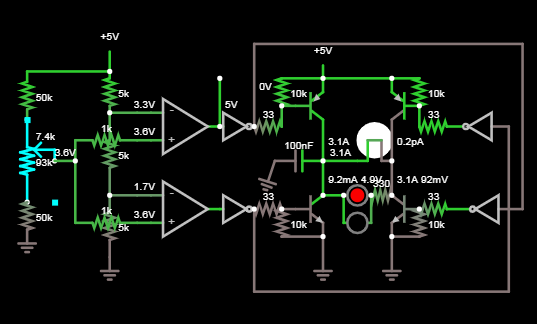
Without knowing your motor specs, here's an improved design I just made. (using a lamp for a load)

Theory of Op
Can you see how the dead band is controlled by middle R ratio, somewhat like a 555 with 5K+5K=5K? Although this seems like a lot, depending on the R values above and below the Pot (or different light sensors) may be small compared the to 3 decade or more dynamic range of the sensors. Somehow another sensor is needed to disable "hunting" in the dark. This could be accomplished with equal R values added across each sensor to limit the dark R value, so the result is in the dead band in the middle. This is done by measurement of R at twilight or on overcast weather.
The middle R reduces the deadband, critical to the decision threshold when to move and use motor energy. You must adjust this to meet your hysteresis spec. If the two sensors are not matched, the motor alignment may be offset which must be offset by the upper or lower R value or matching the sensor sensitivity.
This was designed for any standard bipolar Dual Comparators or Op Amps, so that 1.5V offset to rail is tolerant to the inverter input logic threshold at Vss/2. 5V logic may have 50 or 25 Ohm drivers (Vol/Iol=R) so 33 Ohm was added to limit base current, to drive motor coils with DCR of > 2 ohms . But if 5V motor DCR is much less then 2 ohms then 1V logic level FETs or superbeta BJTs from Diodes Inc must be used. Also Comparators need a 10k pull up resistor are faster to turn on but are not necessary but most OA's can handle a wide enough input voltage ranges.
The cap on left side of bridge to ground is to shunt potential driver-oscillations when both transition to off. ( optional)
The 5V 5W bulb also simulates motor surge current (10x) heating up the bulb as it starts to move with full 5V across the 5V motor. If Vcc is greater than 5V the CMOS drivers must also change and FETS be used as high voltage CMOS (>5.5V) also have high ohm drivers (Vol/Iol) which may not drive PNP drivers with enough base current.
The Red + Yellow (in opposite polarity) LED indicators across the motor are optional and share a current limiting resistor for brightness.
Also, power diodes to each rail are necessary on either side of the motor ( not shown for simplicity) to clamp turn-off motor spikes and return the current to Vcc, Vee ( 5V, 0V) and also stops the motor faster rather than it generating back EMF into the transistors.
Also not shown ( for simplicity) are decoupling caps to reduce RF or Vcc motor noise to each comparator +/- input node, such as 0.1uF to ground.
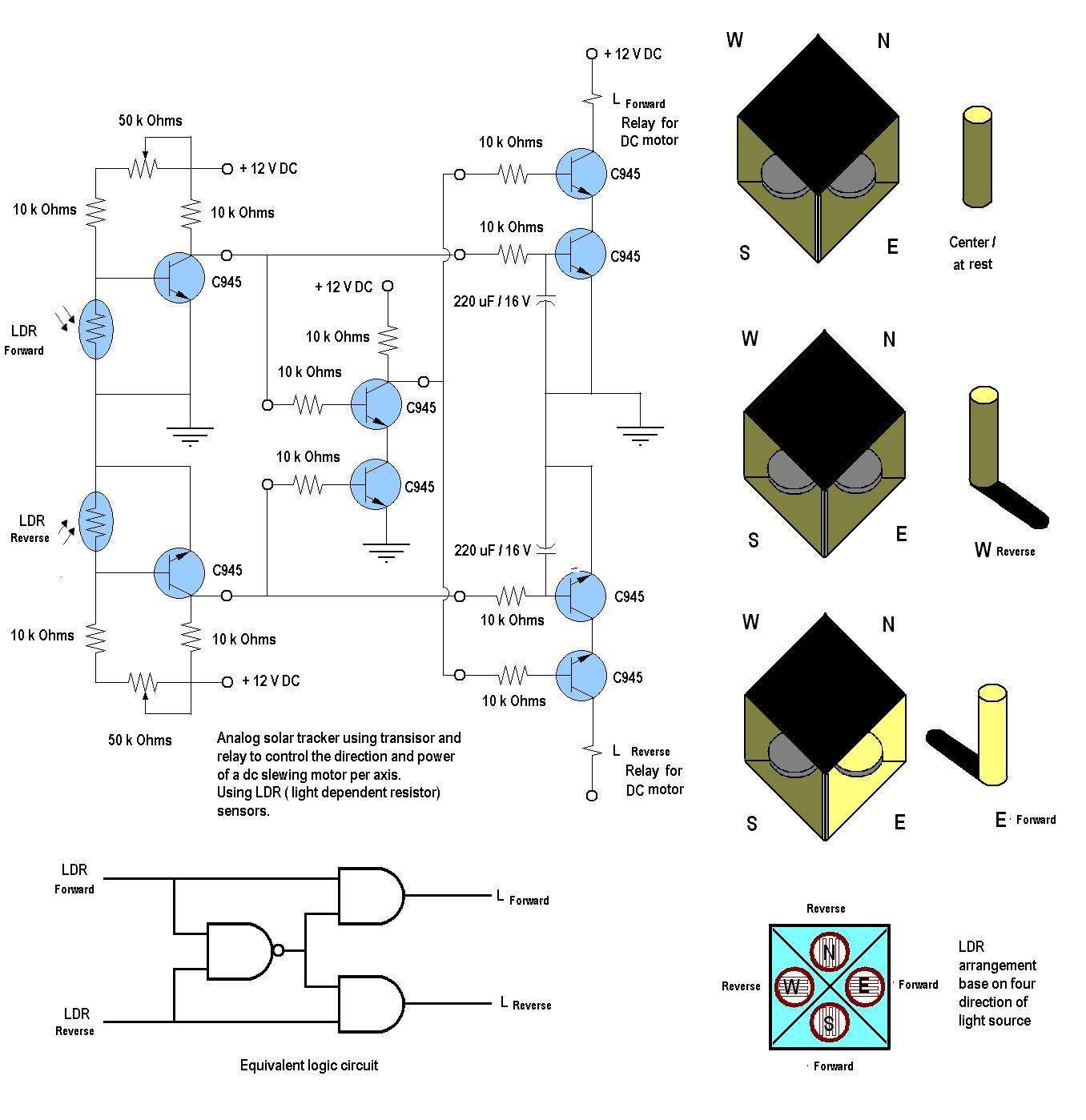
 from: https://www.electroschematics.com/8019/diy-solar-tracker-system/

?button on the editor toolbar that explains the markdown syntax. Press 2 x <Enter> to force a paragraph break and before and after lists which are started with-or1.(both are followed with a space). \$\endgroup\$