1
\$\begingroup\$

I can't seem to grasp how to calculate the values for a common emitter with a load resistance, to cascade an amplifier in multiple stages.

I'm trying to obtain an 8.5-9Vptp output from a 12V supply on a 5520 ohm load resistance. Not trying to achieve much gain since it can be achieved in earlier stages so ~5. I took:

Ic = 10mA

DC emitter 0.5V about ground

Vce min = 1V

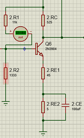
This is what I've got

enter image description here

However, once I actually built the circuit on a breadboard the output ended up being 4Vptp, half of what I actually had in the simulation. What am I doing wrong?

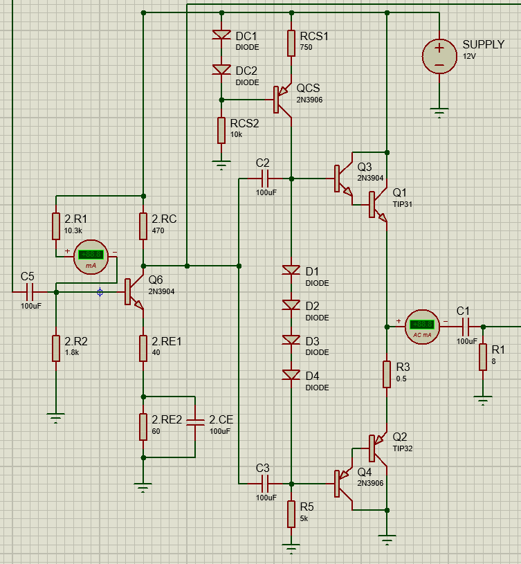
Complete circuit: enter image description here

\$\endgroup\$
1
  • \$\begingroup\$ Comments are not for extended discussion; this conversation has been moved to chat. Any conclusions reached should be edited back into the question and/or any answer(s). \$\endgroup\$
    – Dave Tweed
    Commented May 9, 2019 at 11:18

1 Answer 1

1
\$\begingroup\$

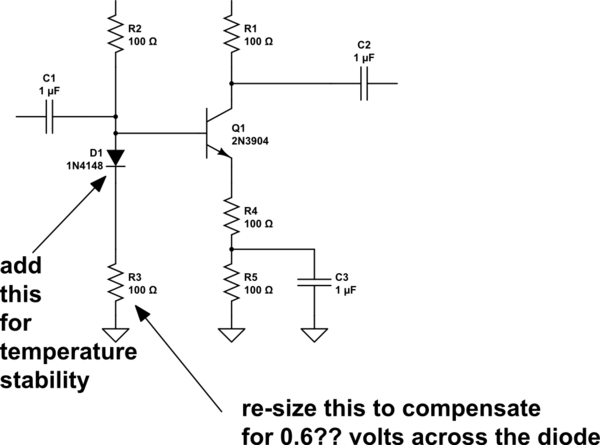
For temperature stability, and the wide output Volts PeakPeak, I'd consider this

schematic

simulate this circuit – Schematic created using CircuitLab

\$\endgroup\$
3
  • 1
    \$\begingroup\$ Maybe add some description for why D1 and why R3 would need to be resized ? \$\endgroup\$
    – efox29
    Commented May 8, 2019 at 20:34
  • \$\begingroup\$ 100 ohms for R2 and R3 are awful low resistance. why would you want so much current flowing down that branch and also have your input impedance so low? \$\endgroup\$ Commented May 8, 2019 at 20:55
  • \$\begingroup\$ his resistor values are different, between the 2 versions of the 5X amplifier; thus the OP can replace the 100 ohms with what he finds will perform correct biasing and gain-setting. \$\endgroup\$ Commented May 8, 2019 at 21:16

Your Answer

By clicking “Post Your Answer”, you agree to our terms of service and acknowledge you have read our privacy policy.

Not the answer you're looking for? Browse other questions tagged or ask your own question.