I have been trying to convert 8bit binary to 8bit BCD. The circuit I have been working on is below:
 I built a 4bit binary to 5bit BCD converter using a similar truth table like the one here:

Do I need a bigger truth table if I am going to design an 8bit binary to 8bit BCD converter? Also, are there any other ways I can create the converter circuit? Your help is much appreciated.
-
\$\begingroup\$ You have 2 7-segment displays, which can handle decimal 0 to 99. 2^7 = 128. So at best you will have a 7 bit binary to 8 bit BCD. So you will need a bigger truth table. \$\endgroup\$– StainlessSteelRatCommented May 29, 2019 at 13:25
-
\$\begingroup\$ @StainlessSteelRat yeah I did the truth table. Its massive and I don't really know how I can get the K-maps for it. \$\endgroup\$– AugieJavax98Commented May 29, 2019 at 14:09
-
1\$\begingroup\$ @AugieJavax98 Still looking for some ideas? There are two easy and completely different ones I can imagine. \$\endgroup\$– jonkCommented May 31, 2019 at 1:26
3 Answers
I'll suggest the more obvious of the two ideas that came to mind. If you haven't already done so, take a look at the double dabble algorithm for conversion. I'll use it as the basis for the following schematics (there are two.)
This first schematic accepts a binary value and leaves it unchanged if the value is \$\le 4\$. Otherwise, it adds \$3\$ to the binary input. There are some assumed illegal input values: \$10-15\$. But it doesn't really matter what happens there. So adding \$3\$ in those cases is fine.

simulate this circuit – Schematic created using CircuitLab
The second schematic uses the above circuit (named PLUS3 below), repeatedly:

That's all there is to implementing the algorithm documented on the Wiki page mentioned above.
Please do note that the output is 10-bit (or 12-bit if you don't mind going there.) But not 8-bit. (At least 10 bits are required for full conversion.) If you don't need the hundreds, then throw away those you don't need.
Note
Also see this more recent post on a related question.
-
\$\begingroup\$ I'm curious - how did you arrive at the first circuit of the plus three module? I'm writing another answer for alternative implementations. \$\endgroup\$– qwrCommented May 28, 2020 at 5:39
-
\$\begingroup\$ @qwr My recollection is that I looked at the initial brute force logic and felt it "could be helped" a bit, toyed with it just for a few minutes and felt "good enough" with what resulted to post it. I probably should have spent more time on it. Might have been able to shorten the longest path, if I had. But I didn't spend the time. I would probably like to see what you develop. It's likely a lot better. Also, look here where I rehashed this old horse, again. \$\endgroup\$– jonkCommented May 28, 2020 at 6:02
-
\$\begingroup\$ Your design uses impressively few circuits but my concern is the maximum delay path (naively counting 8 gates and a half adder). I think a decoder is simple to implement and has less latency. One could create one easily from the DNF equations. And if we include logic for detecting when input is >=5 and multiplexing, the resulting logic is even simpler. \$\endgroup\$– qwrCommented May 28, 2020 at 6:09
-
\$\begingroup\$ @qwr Agreed. I'd like to see what you write, when you write it. I think you are right about the decoder. \$\endgroup\$– jonkCommented May 28, 2020 at 6:16
-
\$\begingroup\$ this is my result messing around with Digital. electronics.stackexchange.com/a/502347/124362 If you're clever you might be able to reuse gates since DNF lists each bit independently. \$\endgroup\$– qwrCommented May 28, 2020 at 6:25
Supplement to my full answer:
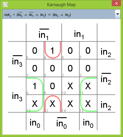
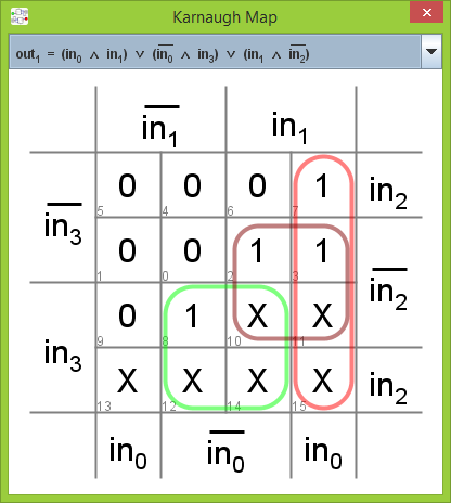
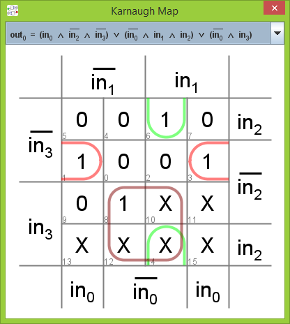
Digital can convert the truth table to disjunctive normal form and draw K-maps for each output bit.
-
\$\begingroup\$ And this, too, now that I see it. Thanks. I only wish you could have placed some of that side by side. It's a bit "long" in the vertical direction. \$\endgroup\$– jonkCommented May 28, 2020 at 6:32
When doing arithmetic, K-maps are less useful than other techniques — basically, they are "too general" when doing something as specific as "sometimes I need to add 6 to a number".
Yes, you'll eventually get a correct answer after a lot of effort — and a lot of opportunities for errors to creep into the process. But if you think in terms of comparators and adders to begin with, you'll find that this is a much more direct approach.
-
\$\begingroup\$ Using the comparator and adder method, I can do the shift add 3 process and get my result right? \$\endgroup\$ Commented May 29, 2019 at 11:18
-
\$\begingroup\$ I don't understand the question. There are many ways to implement binary-to-BCD conversion. Have you searched the Web for techniques? \$\endgroup\$ Commented May 29, 2019 at 11:25
-
\$\begingroup\$ What I need to do is build a converter circuit that converts 8bit binary to 8bit BCD. I have searched the web, but most of what I've found are techniques for 4bit binary to 5bit BCD. To add on, all of the techniques involved the use of truth tables and K-maps. \$\endgroup\$ Commented May 29, 2019 at 11:32


