With commonly used bridge schematics, the operation with optocouplers are like on and off, like without smooth transitions under PWM. If opto with additional 10-12volts to gates via them, are excluded, and 5v logic are given to gates only, it works as it is required. As I get it, it works like in linear mode. But what can be done to eleminate the on'off operaton of the h-bridge with optos?
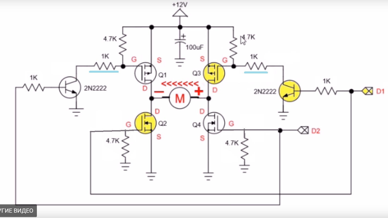
The second schematics gives the full power constantly.
With the first, if opto are changed to 2n2222 it makes it weaker.
Mosfets P-channel - IRF4905, and N-channel -IRF3205
-
1\$\begingroup\$ What is your PWM frequency? Many optocouplers are notoriously slow if you don't take any precautions. \$\endgroup\$– Richard the SpacecatCommented May 29, 2019 at 12:33
-
4\$\begingroup\$ Your question seems to be based in misunderstanding the goal: linear operation is not desireable, as it turns power into heat. To the greatest extent possible, your system should only ever be fully on or off. Moderation is via the time average of the PWM. \$\endgroup\$– Chris StrattonCommented May 29, 2019 at 12:33
-
\$\begingroup\$ I put from 4khz to 20khz. Know that 817 optocoupler is best till 8khz. Know about the linear mode are not good. But why then with 2n2222 all the same? Only right gate drivers will solve? Also if such state with transistor, that should be all the same with transistor exit optos like 4n35? \$\endgroup\$– SiebenCommented May 29, 2019 at 12:54
4 Answers
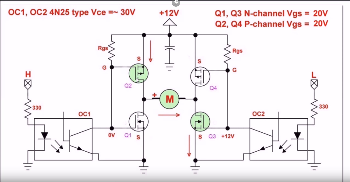
Schematic 1 is only useful for low voltage motors as the Pch and Nch FETs will both be conducting heavily (shoot-thru) at some Vdd/2 voltage applied to the gates. E.g. Vdd= 2Vgs(th) and is very device specific. There are only 2 gate drivers here which is a serious limitation for simplicity. It might be improved with the same Rgate divider or better with 4 Opto’s in order to have a 1us deadtime during commutation. Then some snubber or clamp diodes are needed in FETs or outside.
Schematic 2 is better with 4 gate voltages separated by resistor dividers as level shifters to avoid shoot-thru but is still a poor design but simple.
More common is all Nch FETs using high side for direction and low side for PWM which also feeds a Vboost to get a higher gate voltage than Vdd. Dead-times of 0.5us are common and depend on motor inductance.
In all cases the RdsOn must be much less than the motor DC resistance or DCR.
The concept in all cases is to avoid linear mode and switch OFF faster than ON often to create this dead-time. That is done with IC drivers or a diode+ smaller R in parallel with another R to gate. (not shown in either example here.)
The way I see it, by having the opto couplers connected that way you will need both PWMs to be synchronised.
Another thing is that you are missing is a path for the internal capacitors of the mosfets to dissipate their charge when the opto couplers are off.
Will explain more, why tell about “worked fine in linear mode”. Yes, want to get away with simplicity for the DIY FFB wheel driver with these schematics). https://youtu.be/e7uPNGBH0ZI As I get it, it is required alternatively, current reduction from the PSU to get the smooth operation of the feedback. May be. And in my example, the current reduction was made in MOSFETs))) So they did not last longer, and especially with fast direction changes. With only two optos, and 2 small separate 12v batteries on the gates via them, to the second schematic, that was fine but with no smooth operation in center position of a wheel. But it doesn’t burned at least for the time it was tested, (a number or so of a ride on tracks in racing sim) compared to “no optos” etc. This issue, of on/off center forced to search for smth else. Also putted on N-side mosfet the IRLB3034. Was a bit better, cause it’s a logic level, but tried it without any gate drivers and the currents, did, not a good things out there with this build. The motor that is used is MY1025. A rather big one. Have big stall currents for this driver guess any way. Use 12v12.5PSU for it with 4F capacitor also in parallel to 12v supply. Find about that high side should be on/off, and pwm only to low side. That will not do a mess with currents etc. http://www.irf.com/electronics/topology-fundamentals So then gonna switch to this approach somehow. The Pwm + Dir mode. For the present state, can just the 4 optos be made, so that it can solve the issue? https://i.ibb.co/dPbYDwT/Screen-Shot01883.jpg Or it will be all the same? With that shoot through etc…. P.S. do have the Schottky diodes out there, they are just not in the schematic. And just 4.7-10 ohm resistor on gate for mosfets not to ring. But without a diode.
Also good info, but haven’t tested that with those IR2110 drivers IC. http://tahmidmc.blogspot.com/2013/01/using-high-low-side-driver-ir2110-with.html http://tahmidmc.blogspot.com/2013/02/n-channel-mosfet-high-side-drive-when.html http://tahmidmc.blogspot.com/2012/12/low-side-mosfet-drive-circuits-and_23.html
Was a try with several mosfets in parallel for each of the slots. But there were some mess somewhere in a board, so i put them away also to reduce the issues to be checked)
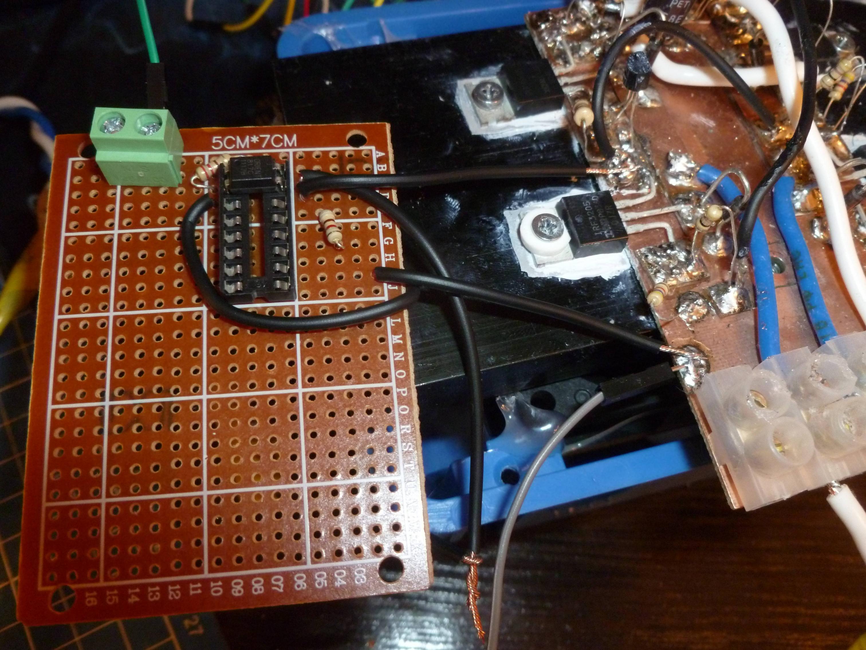
Issue with on and off of the driver with optrons, is seems to be solved. And appeared to be simple. It was a wrong connection of the optrons input led to the ground of the whole system. Instead of connecting it back to arduino's GND only. Thus making isolation and arduino protection) And what's more over, lack of right connection, this just gives the linear voltage controll of the mosfet, without the pwm at all) :D:cool: That's why it all was so)


