2
\$\begingroup\$

schematic

simulate this circuit – Schematic created using CircuitLab

I am kind of new to building my own electronics.

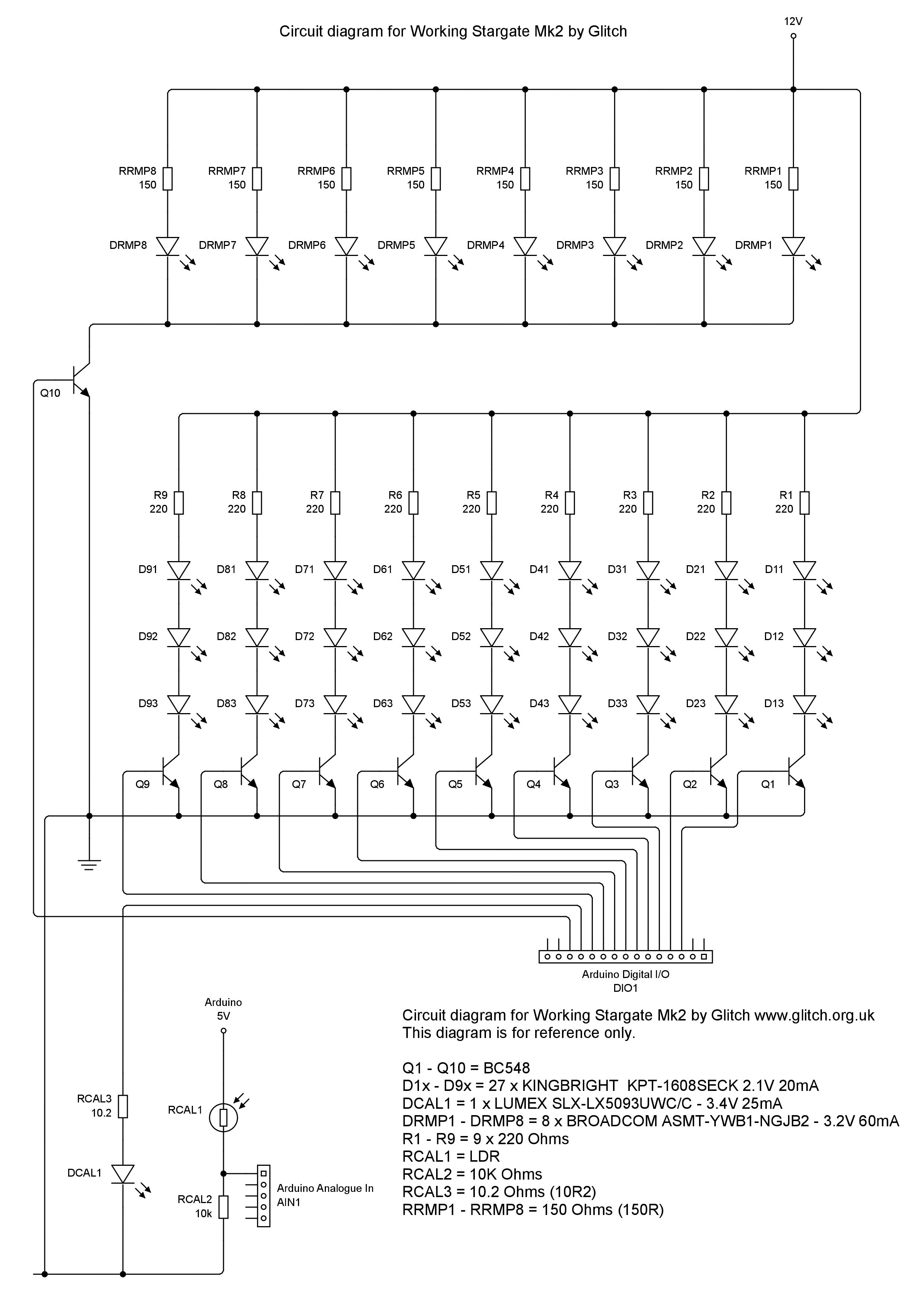
I am building a stargate with 3D printed parts. When I soldered all the LEDs together, I connected them in series (9 sets of 3 LEDs) with a common ground as that is how I had seen others do it in the 3D printing community. After getting all of the soldering done, I glued the cover on it and when testing realized that in series the rduino doesn't have enough power to light the LEDs completely, they do turn on but barely visible.

It's too late to go back and re-solder them in parallel since I have already glued all the plastic parts together using 3D Gloop which bonds the PLA plastic together chemically.

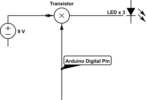
What I need to do is provide a 9V charge to each set of 3 lights and I understand from my google searches and youtube that I can do that with transistors.

All the videos and information I have seen show the transistor using the ground between the collector and emitter to regulate the flow with the base connected to the digital pin of the Arduino to activate it. Since I wired all the sets of LEDs to a common ground and they need to be turned on individually, I need to run the 9V through the transistors to the 9 sets of LEDs individually and I'm really not sure what type of resistor to use.

The LEDs already have 220 ohm resistors connected inside the stargate if that helps. Any assistance would be appreciated since this is a graduation present for my nephew.

Original schematic

\$\endgroup\$
18
  • 4
    \$\begingroup\$ This is why you should always test the circuit before putting it in an enclosure! That being said, do you have any access to the inside of the enclosure? or do you only now have access to the wires going in? A schematic and a photo would help here \$\endgroup\$
    – MCG
    Commented Jun 5, 2019 at 7:46
  • \$\begingroup\$ I only have access to the wires going in, added a picture. Don't have a schematic with me right now. \$\endgroup\$ Commented Jun 5, 2019 at 8:01
  • \$\begingroup\$ There is a built in schematic editor here. If you edit the question you can draw one. Just press ctrl+M, or click the schematic editor symbol. And your picture is before it is assembled. What would be helpful is a properly drawn schematic, and a picture of it as it is now, so we can see what wires you have access to, and you can point them out ini the schematic \$\endgroup\$
    – MCG
    Commented Jun 5, 2019 at 8:23
  • \$\begingroup\$ Added a schematic, hope that helps \$\endgroup\$ Commented Jun 5, 2019 at 8:38
  • \$\begingroup\$ I meant a schematic of what you have right now, rather than what you want. Then label on the schematic what wires are actually available \$\endgroup\$
    – MCG
    Commented Jun 5, 2019 at 8:44

3 Answers 3

3
\$\begingroup\$

It seems that when you were assembling your circuit, you forgot to add the transistors Q1-Q9 in your circuit. These are needed to allow the Arduino to control when the LEDs turn on/off without supplying them directly, by wiring them to the transistor base, hence you won't need to worry about how much current is available from the Arduino pin.

If you have access to the GND wires from each column of LEDs, this is where you should place the transistor.

Once you have fitted it, you should find that you can control the LEDs with the Arduino pins.

If making any similar projects in the future and you are following a schematic, read it carefully, and perhaps do some Googling or ask here about any parts of a circuit you are unsure about. It is always good to try and understand how something works before putting it together, as that way if you run into problems, it makes fault finding a lot easier.

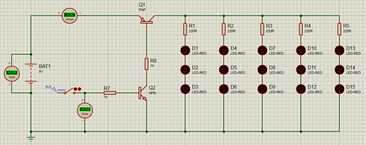
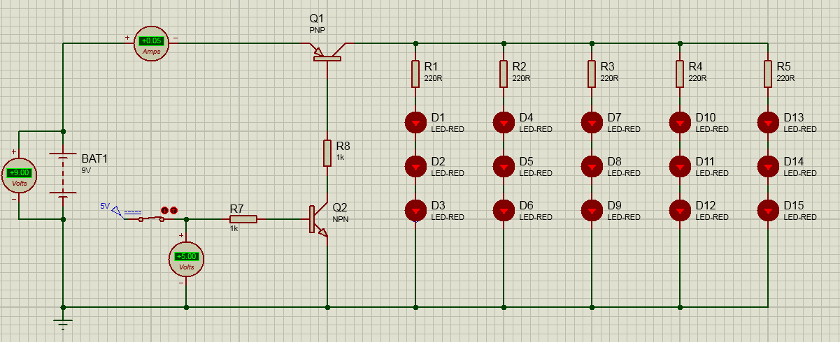
If you have just a single common GND, then you will need to have a high side switch. You can use a PNP/NPN pair to do something like this. I have simulated the circuit for you so you can see how to connect it. This is probably the easiest, and cheapest way to resolve your issue.

To have the LEDs OFF:

enter image description here

And to turn them ON:

enter image description here

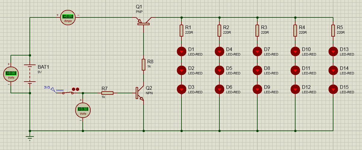
The logic pin (that switches from 0 to 1) will be a 5V Arduino pin. If you do not have 5V available, it will also work with 3.3V:

enter image description here

This could also be a useful transistor configuration to remember if you ever need to switch a higher voltage for future circuits.

\$\endgroup\$
10
  • \$\begingroup\$ Thank you so much for your input. Given that I have hooked them all to the same ground, is it still possible for them to work properly if I add the transistor before the LEDs in the circuit instead of after? Also, I will be more careful in the future, this is really my first project and I really appreciate the advice. \$\endgroup\$ Commented Jun 5, 2019 at 9:53
  • \$\begingroup\$ @DanielBrandenburg Oh I see! So you only have 1 common GND wire that you have access to? You haven't got a separate GND from each column and tied them together outside the stargate? \$\endgroup\$
    – MCG
    Commented Jun 5, 2019 at 10:04
  • \$\begingroup\$ correct, I connected them all to the same GND wire when I soldered them together inside the gate. There was very little space for the wires and I thought it would make thing easier, I learned my lesson, lol. \$\endgroup\$ Commented Jun 5, 2019 at 10:13
  • \$\begingroup\$ @DanielBrandenburg I have edited my answer with something that should work for you. Please note that you will need to choose an NPN transistor that will be able to handle the current. The BC548 will probably get too hot with this circuit. \$\endgroup\$
    – MCG
    Commented Jun 5, 2019 at 10:33
  • \$\begingroup\$ will that light them all up at once, or each set individually, or am I missing something? I mean I understand the concept I think, To do it individually I would just apply this circuit to each of the sets of 3 LEDs. I just need to determine the proper Transistor? \$\endgroup\$ Commented Jun 5, 2019 at 11:03
1
\$\begingroup\$

In addition to the answers you've already received, here is my suggestion.

schematic

simulate this circuit – Schematic created using CircuitLab

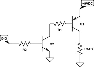
Resistor \$R_{LOAD}\$ is a "dummy" component; it is a placeholder for the actual circuit that you want to turn ON|OFF via Q1. To solve for the values of the "current limiting" resistors R1 and R2 proceed as follows.

  1. Determine the required current through the load, \$I_{LOAD}\$. For the purposes of this example assume \$I_{LOAD}=20\;mA\$. (n.b. I'm assuming the LOAD circuit has one or more components that limit the LOAD current to 20 mA when Q1 is ON.)
  2. For Q1 choose a PNP transistor whose rated collector current \$I_C\ge2I_{LOAD}\$. I'll choose for Q1 an ON Semiconductor 2N3906 PNP transistor whose \$I_C=200\;mA\$.
  3. Using Q1's data sheet determine the forward current gain when Q1 is operating in saturation mode (fully ON): \$\beta_{SAT}=10\$.
  4. Calculate Q1's base current when Q1 is operating in saturation mode: $$ Q1.I_{B(SAT)}=\frac{Q1.I_{C(SAT)}}{Q1.\beta_{SAT}}=\frac{20\;mA}{10}=2\;mA $$
  5. For Q2 chose an NPN transistor whose rated collector current \$I_C\ge 2\cdot Q1.I_{B(SAT)}\$. I'll chose an ON Semiconductor 2N3904 NPN transistor whose \$I_C=200\;mA\$.
  6. Using Q2's data sheet determine the forward current gain when Q2 is operating in saturation mode (fully ON): \$\beta_{SAT}=10\$.
  7. Calculate Q2's base current when Q2 is operating in saturation mode: $$ Q2.I_{B(SAT)}=\frac{Q2.I_{C(SAT)}}{Q2.\beta_{SAT}}=\frac{2\;mA}{10}=200\;\mu A $$
  8. Solve for R1. (n.b. Use the 2N3904 and 2N3906 data sheets to find values for \$V_{CE(SAT)}\$ and \$V_{BE(SAT)}\$.) (n.b. On a PNP transistor, current flows OUT of the transistor's base lead, and \$V_{BE(SAT)}\lt0\;V\$, and \$V_{EB(SAT)}=-V_{BE(SAT)}\$.) $$ R1=\frac{V_{R1}}{I_{R1}} \\=\frac{V_{CC}-Q1.V_{EB(sat)}-Q2.V_{CE(sat)}}{Q1.I_{B(sat)}} \\=\frac{9\;V-0.8\;V-0.05\;V}{2\;mA} \\=4.08\;k\Omega $$
  9. Choose R1's value as \$3.9\;k\Omega\pm5\;\%\$. (n.b. Calculate R1's power dissipation when Q2 is ON: \$P=I^2R\$. Choose for R1 a resistor whose power dissipation spec is >=2x its calculated power dissipation.)
  10. Solve for R2. (n.b. Use the microcontroller's data sheet to find \$V_{OH}\$ for the DIO pin. For example, assume we are using a Microchip Technology ATmega328P microcontroller and 5 V logic; see Chapter 30 "Electrical Specifications" in the data sheet. Use the 2N3904 data sheet to find \$V_{BE(SAT)}\$.) $$ R2=\frac{V_{R2}}{I_{R2}} \\=\frac{DIO.V_{OH}-Q2.V_{BE(sat)}}{Q2.I_{B(sat)}} \\=\frac{4.2\;V-0.7\;V}{200\;\mu A} \\=17.5\;k\Omega $$
  11. Choose R2's value as \$18\;k\Omega\pm5\;\%\$. (n.b. Calculate R2's power dissipation when Q2 is ON. Choose for R2 a resistor whose power dissipation spec is >=2x its calculated power dissipation.)
\$\endgroup\$
1
  • \$\begingroup\$ That is a lot more information than I thought I would get on here. As soon as my transistor kit gets here, I will be sure to reference this information while breadboarding my circuit. Thank you. \$\endgroup\$ Commented Jun 6, 2019 at 1:13
0
\$\begingroup\$

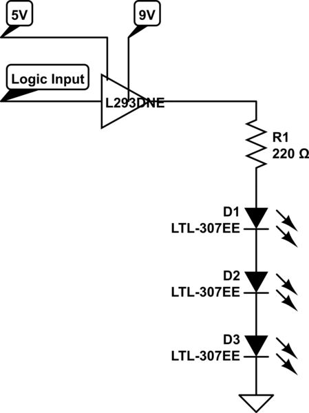
It is unfortunate that the LED common side is ground, so you will need a high-side driver which requires more than one transistor per circuit. Or, you could use an IC that has multiple drivers. I have seen up to 8 per IC, this one has 4. Assuming that you have 5V available, three of these would be needed for your 9 LED circuits. This is a little overkill since it will drive both high and low, but right now I can't find a suitable high-side only driver. https://www.digikey.com/product-detail/en/texas-instruments/L293DNE/296-9518-5-ND/379724

schematic

simulate this circuit – Schematic created using CircuitLab

\$\endgroup\$
3
  • \$\begingroup\$ How can anyone down-vote this? THIS WILL WORK AND IT USES 3 PARTS INSTEAD OF 36! (not counting the LEDs and series resistors that are already inside the Stargate) \$\endgroup\$
    – Mattman944
    Commented Jun 5, 2019 at 16:00
  • \$\begingroup\$ I'm wondering the same thing. It will indeed work. I upvoted the answer. Definitely didn't deserve a downvote. Would be nice if people left comments explaining their reasons! \$\endgroup\$
    – MCG
    Commented Jun 5, 2019 at 22:28
  • \$\begingroup\$ I found the idea interesting myself, wouldn't have down voted it. Wouldn't have a clue how to implement it, but I have learned a lot from my mistakes since asking this question and appreciate your response. \$\endgroup\$ Commented Jun 6, 2019 at 1:12

Your Answer

By clicking “Post Your Answer”, you agree to our terms of service and acknowledge you have read our privacy policy.

Not the answer you're looking for? Browse other questions tagged or ask your own question.