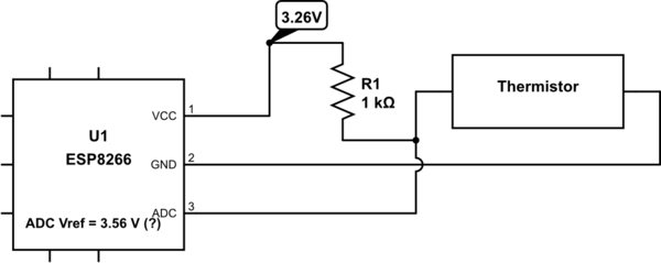
In addition to the other comments/answers you've received to date, the figure you've added to your original post shows a design flaw that must be addressed. By my calculations, if VCC's nominal voltage is 3.3 V, then for thermistor temperature values of
T = [-40 0 25 40] (°C)
the corresponding nominal output voltages V_OUT from your circuit are
V_OUT = [ 3.2667 3.0633 2.7211 2.4198 ] (VDC)
(n.b. V_OUT is the voltage that's connected to the ADC input pin.) According to Espressif's data sheet for the ESP8266EX (p. 16):
The [ADC] input voltage range is 0 to 1.0V when TOUT is connected to external circuit.
So these V_OUT voltages are too high and could possibly damage the ADC input.
FWIW, if you swap the resistor and thermistor positions so that the circuit topology becomes
VCC -- thermistor --(V_OUT)-- resistor -- GND
the resulting nominal V_OUT voltages applied to the ADC for the aforementioned thermistor temperatures are
V_OUT = [ 0.0333 0.2367 0.5789 0.8802 ] (VDC)
which would be okay. This topology also ensures that V_OUT increases with increasing thermistor temperature, AND the worst-case resolution (not taking into consideration other error sources--e.g., component tolerances) would be about 0.5 °C/bit at the -40°C end, which isn't too terrible.
In Espressif's FAQ for the ESP8266 (scroll down to the "Peripherals" section), the item titled "What should I use the internal ADC for?" states (emphasis added).
The internal ADC can be used for temperature sensing or sensing approximate current drawn by external devices. Note that because the ADC readings are prone to noise, it should only be used for applications where high accuracy is not required. For example, thermal cut-off mechanisms, etc.
Additional considerations related to this ^^^ topic regarding ways to reduce the errors in your measurements are addressed by the other respondents to your post--e.g., tightening the component tolerances, using a ratiometric measurement method (which would likely require an external ADC chip with at least two inputs to measure VCC and V_OUT), etc.
The FAQ topic titled "How accurate is the internal ADC?" states (emphasis added):
If a high accuracy is required, please use system_adc_fast_read API. But RF circuitry should be shut down before measuring and Wi-Fi will be disconnected. For an relatively lower accuracy when readings’ difference of 1 or 2 can be tolerated, we recommend users to configure Wi-Fi to non-sleep mode wifi_set_sleep_type(NONE_SLEEP_T).
For lower accuracy, the user may enter sleep mode. Power consumption is lower in this case.
When the Wi-Fi transmitter is howling RF energy, the power that's drawn from the power supply by the RF transmitter, and the electromagnetic radiation emitted by the RF transmitter+antenna adds (possibly substantial) electrical noise to a) the board's power buses (e.g., VCC voltage droop), and b) your nearby resistor + thermistor + connecting wires circuit. Note that your component leads and hookup wires will act as antennas and will receive some of the RF energy that's emitted by the Wi-Fi transmitter. IOW, power bus voltage droops and unwanted absorption of RF energy in the power bus and in your components are other significant noise sources that must be managed if you want your temperature measurements to exhibit reproducibility, precision, and accuracy.

