4
\$\begingroup\$

This is the datasheet of TPS7A8101 LDO I am analyzing. In the datasheet, start-up time of the LDO is given as 80 ms for given conditions. enter image description here

My question is, how can I calculate the turn-off time of the LDO. I was doing a shut-down timing sequence diagram for my circuit and came across this LDO. I believe LTSpice simulation can get an idea of turn-off time. But not sure about that.

How can I find the turn off time of an LDO?

\$\endgroup\$
1
  • 2
    \$\begingroup\$ I doubt the LDO will pull-down the outpout when it is switched off. Which means the off time is mostly your bulk capacitor which has to discharge through the load. \$\endgroup\$
    – Oldfart
    Commented Jun 11, 2019 at 15:38

3 Answers 3

4
\$\begingroup\$

This particular voltage regulator has no active clamping function so you're looking at some function of the output capacitance input voltage waveform and regulator characteristics.

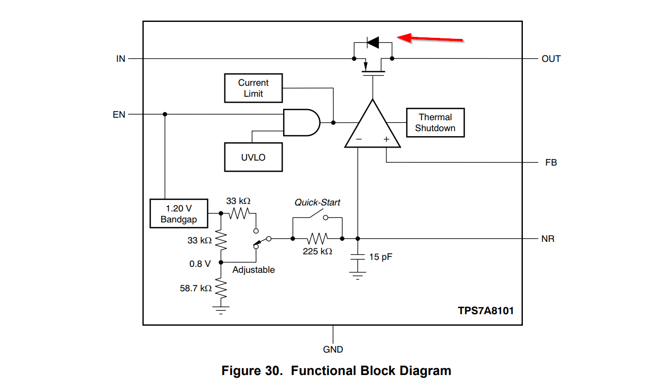
Case 1: If you actively pull the power input to the regulator down to 0V, the output capacitance will primarily discharge through the pass transistor body diode, at least down to 0.7V or so. See the block diagram below, which clearly shows a diode directly between output and input:
enter image description here

Case 2: If you open the input then the input capacitance and output capacitance will discharge through the bias network in the chip, perhaps via the body diode in part, and whatever load you've got on the output.

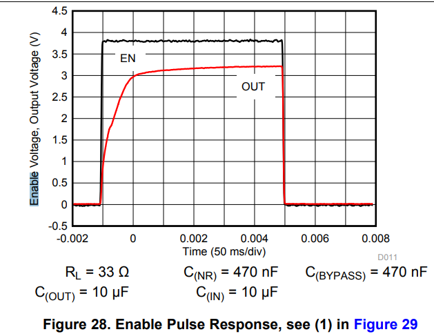
Case 3: If you disable the regulator through the enable input (with input power still applied) it will probably depend almost entirely upon the load current and output capacitance. The datasheet shows the typical output response to enable turning off, but it's with a rather low load resistance (33\$\Omega\$) so the RC time constant of the output capacitor and load is only 330usec which doesn't really show up at 50ms/div.
enter image description here

With the recommended feedback resistors and no other load, and with 10uF the time constant is more than 400ms so it could take more than 1 second to to drop down to << 1V.

If you need to have the regulator output drop down to some specific maximum voltage in a certain period of time under specific conditions, you can test a sample and add a large safety margin or buy a part that is specified for that kind of requirement.

For example, the LT3063 has an active discharge function that will take a 10uF output load capacitance down to < 10% of output voltage in 750us typical, 2ms maximum for enable controlled shutdown.

\$\endgroup\$
2
  • \$\begingroup\$ Could you please share how you come to 0.7 V when discharging ? \$\endgroup\$
    – vt673
    Commented Jun 11, 2019 at 15:56
  • 1
    \$\begingroup\$ @vt673 See edit above. The forward voltage of a diode is about 0.7V. \$\endgroup\$ Commented Jun 11, 2019 at 16:01
3
\$\begingroup\$

Because it is so variable it is not listed in the datasheet. This value will be very dependent on the load. This is probably not a problem that you could predict but place bounds on. The RC time constant of the load and bypass caps would be an "upper bound" on time. If your load has transistors in it, it could be a really complex problem because the amount of current/voltage can vary as the device powers off (from what I've seen anyway).

\$\endgroup\$
1
\$\begingroup\$

As Laptop2d said, that's beyond the scope of the datasheet of the IC: You'd need to discharge all the output capacitors through a load, and since neither capacitors nor the load are part of the IC, it has no influence on how long it'll take.

You could speed things up by shorting the capacitors to ground as soon as you turn off the regulator, but that would need additional external components (mainly: a transistor).

\$\endgroup\$

Your Answer

By clicking “Post Your Answer”, you agree to our terms of service and acknowledge you have read our privacy policy.

Not the answer you're looking for? Browse other questions tagged or ask your own question.