0
\$\begingroup\$

im trying to use ASF to schedule repeated tasks.

using TC4 and TC5:

in atmel start both using generic clock generator 0 (48MHz). both are HAL:DRIVER:Timer

driver init.c is generated automatically by atmel start: enter image description here
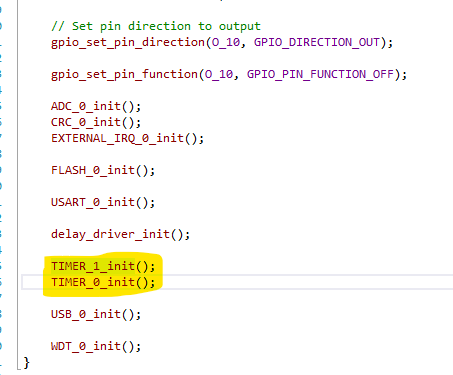
  • timer_1_init = TC4
  • timer_0_init = TC5

when i comment Timer_1_init() ..

timer0 task runs ok.. however, when timer_1_init is called.. the task in tc4 is not called.

i read about tc4 and tc5 have same gclk id so i did this (enable both buses and then enable gclk channel) .. but same issue.. enter image description here
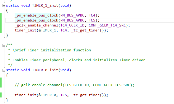
if i comment init of tc4:
- tc5 code works fine if i comment init of tc5:
- tc4 code works fine if i dont comment inits:
- tc5 task works (even if i init tc4 before init of tc5)

========= edit section =========

int32_t timer_init(struct timer_descriptor *const descr, void *const hw, struct _timer_hpl_interface *const func)
{
    ASSERT(descr && hw);
    _timer_init(&descr->device, hw);
    descr->time                           = 0;
    descr->device.timer_cb.period_expired = timer_process_counted;

    return ERR_NONE;
}

note device->hw = hw in next func

int32_t _timer_init(struct _timer_device *const device, void *const hw)
{
    int8_t i = get_tc_index(hw);

    device->hw = hw;
    ASSERT(ARRAY_SIZE(_tcs));

    hri_tc_wait_for_sync(hw);
    if (hri_tc_get_CTRLA_reg(hw, TC_CTRLA_ENABLE)) {
        hri_tc_write_CTRLA_reg(hw, 0);
        hri_tc_wait_for_sync(hw);
    }
    hri_tc_write_CTRLA_reg(hw, TC_CTRLA_SWRST);
    hri_tc_wait_for_sync(hw);

    hri_tc_write_CTRLA_reg(hw, _tcs[i].ctrl_a);
    hri_tc_write_DBGCTRL_reg(hw, _tcs[i].dbg_ctrl);
    hri_tc_write_EVCTRL_reg(hw, _tcs[i].event_ctrl);

    if ((_tcs[i].ctrl_a & TC_CTRLA_MODE_Msk) == TC_CTRLA_MODE_COUNT32) {
        hri_tccount32_write_CC_reg(hw, 0, _tcs[i].cc0);
        hri_tccount32_write_CC_reg(hw, 1, _tcs[i].cc1);
    } else if ((_tcs[i].ctrl_a & TC_CTRLA_MODE_Msk) == TC_CTRLA_MODE_COUNT16) {
        hri_tccount16_write_CC_reg(hw, 0, (hri_tccount16_cc_reg_t)_tcs[i].cc0);
        hri_tccount16_write_CC_reg(hw, 1, (hri_tccount16_cc_reg_t)_tcs[i].cc1);
    } else if ((_tcs[i].ctrl_a & TC_CTRLA_MODE_Msk) == TC_CTRLA_MODE_COUNT8) {
        hri_tccount8_write_CC_reg(hw, 0, (hri_tccount8_cc_reg_t)_tcs[i].cc0);
        hri_tccount8_write_CC_reg(hw, 1, (hri_tccount8_cc_reg_t)_tcs[i].cc1);
        hri_tccount8_write_PER_reg(hw, _tcs[i].per);
    }
    hri_tc_set_INTEN_OVF_bit(hw);

    _tc_init_irq_param(hw, (void *)device);
    NVIC_DisableIRQ((IRQn_Type)((uint8_t)TC_IRQ_BASE_INDEX + tc_get_hardware_index(hw)));
    NVIC_ClearPendingIRQ((IRQn_Type)((uint8_t)TC_IRQ_BASE_INDEX + tc_get_hardware_index(hw)));
    NVIC_EnableIRQ((IRQn_Type)((uint8_t)TC_IRQ_BASE_INDEX + tc_get_hardware_index(hw)));

    return ERR_NONE;
}

==============

what causes this problem?

\$\endgroup\$
8
  • \$\begingroup\$ these can be tricky sometimes, for example in sam4e micros the clock sources in the datasheet can be somewhat confusing in this case how is TIMER_0 and TIMER_1 defined? also why are you not enabling the clock in TIMER_0_init in contrast to TIMER_1? \$\endgroup\$
    – diegogmx
    Commented Jun 19, 2019 at 8:05
  • \$\begingroup\$ Timer_1 and Timer_0 to my knowledge are actually empty structures. timer_init() will fill them. \$\endgroup\$ Commented Jun 19, 2019 at 9:03
  • \$\begingroup\$ @diegogmx the code is actually doing both init same, what i showed in the post is actually modified version where i dont setup gclk_enable_channel twice. but that didnt work. i set it back to be both same now \$\endgroup\$ Commented Jun 19, 2019 at 9:11
  • \$\begingroup\$ can i see timer_init? never used atmel start, however in asf 2.x i never use empty structs like that, generally the first argument is the pointer to the peripheral, meaning the first config register addr \$\endgroup\$
    – diegogmx
    Commented Jun 19, 2019 at 9:17
  • \$\begingroup\$ @diegogmx i've edited post in edit section and pasted the two functions called. (timer_init and internal _timer_init) \$\endgroup\$ Commented Jun 19, 2019 at 9:28

1 Answer 1

1
\$\begingroup\$

this is answer from microchip support:

The timer/counter peripheral is actually a set of 16-bit timers, which can be combined to use as 2 32-bit timers.

When paired, the TC peripherals are configured using the registers of the even-numbered TC (TC4 in this case). The odd-numbered partner (TC5) will act as slave, and the Slave bit in the Status register (STATUS.SLAVE) will be set.

The timer middleware in the Atmel Start configures the timer as 32 bit timers by default, hence it is not possible to use both TC4 and TC5 in two instances of Timer middleware, as both of them will be paired to be used as 32-bit timer and TC5 is acting as slave.


to manual change the code generated by atmel start:

// Mode set to 32-bit

#ifndef CONF_TC3_MODE
#define CONF_TC3_MODE TC_CTRLA_MODE_COUNT32_Val
#endif

in hpl_tc_config.h

\$\endgroup\$

Your Answer

By clicking “Post Your Answer”, you agree to our terms of service and acknowledge you have read our privacy policy.

Not the answer you're looking for? Browse other questions tagged or ask your own question.