1
\$\begingroup\$

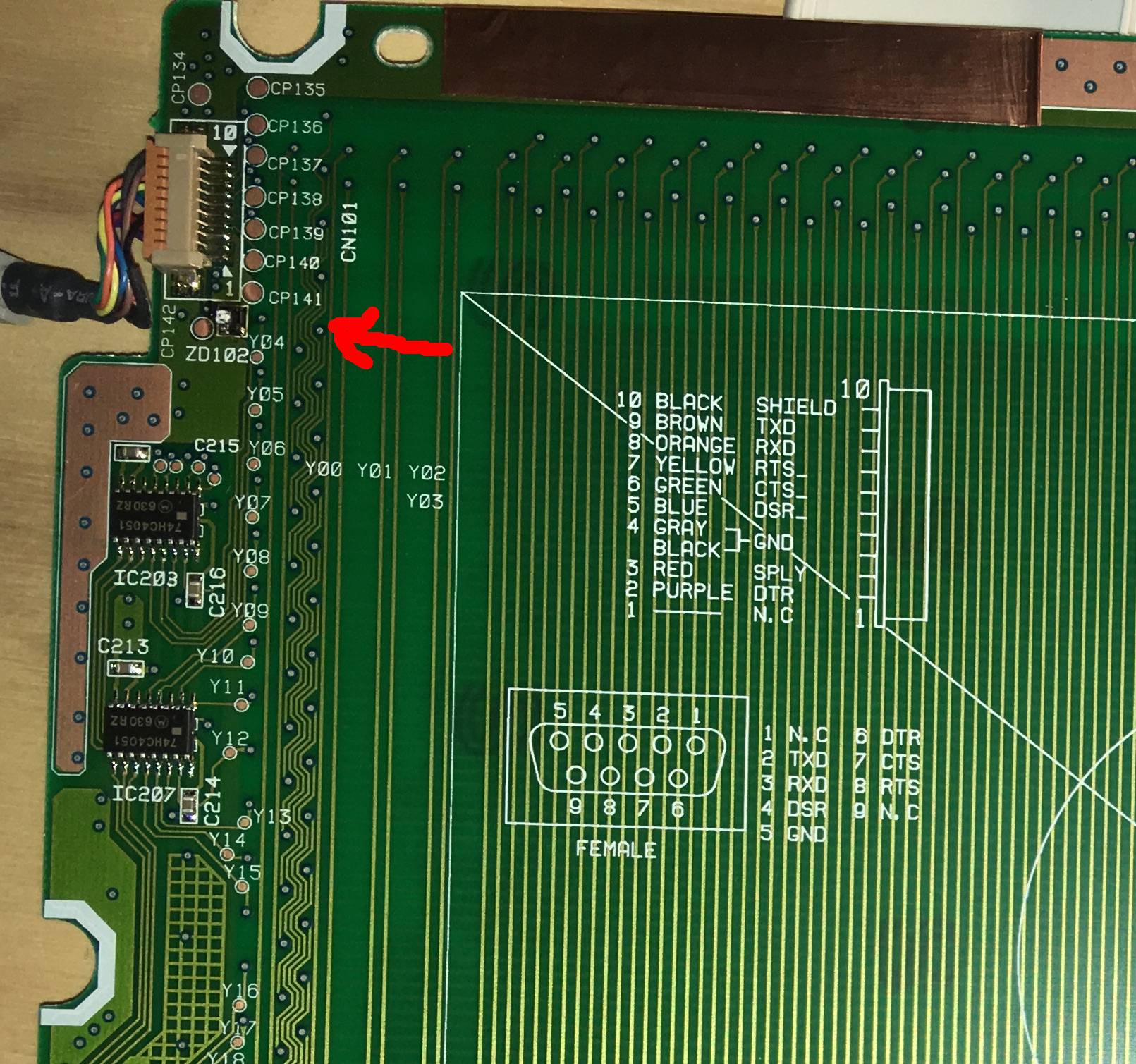
photo of PCB

Part at ZD102 is overloaded with too much current and blown.

It's three legged, with two legs on the south side and 1 on the top.

The left side (white in the picture) is blown and has since crumbled away. There are now clearly three metal legs. I cannot identify any markings nor polarity. ZD102 appears to be a unique location.

I would like to identify and then source the part to solder in place. Or something equivalent. Or something I can salvage from other electronics. There doesn't appear to be any other damage to the motherboard.

This is a Wacom digitizer II UX-0608-R from mid 1990s. DC 9-12v 0.10A.

Appreciate your time.

\$\endgroup\$
11
  • 4
    \$\begingroup\$ Probably a Zener Diode. \$\endgroup\$
    – Andy aka
    Commented Jun 19, 2019 at 10:08
  • \$\begingroup\$ Reasonable that ZD would be Zener Diode, but three legs? \$\endgroup\$
    – rooprob
    Commented Jun 19, 2019 at 10:18
  • 1
    \$\begingroup\$ It could have been 2 diodes in 1 package. \$\endgroup\$
    – Lior Bilia
    Commented Jun 19, 2019 at 10:34
  • 1
    \$\begingroup\$ Go google SOT23 zener diodes. \$\endgroup\$
    – Andy aka
    Commented Jun 19, 2019 at 10:49
  • \$\begingroup\$ Thanks guys. Looks promising. Would you hazard a guess at what spec's given the input voltage of 12v and 100mA. \$\endgroup\$
    – rooprob
    Commented Jun 19, 2019 at 10:57

1 Answer 1

1
\$\begingroup\$

TA7805F can handle up to 35V input voltage. I would remove the diode or use a continuity tester to see if the diode is parallel to the 12V power supply.

Take care, the diode might be shorted so better remove-it from the board.

If it was a Zener it should be with cathode to 12V and anode to ground and a breakdown voltage higher than than maximum voltage of the power supply but lower than the maximum input voltage for any component powered from 12V line.

It seems that the board is double sided so it should be easy to follow the 12V line to see where it goes. I suspect that it goes only to TA7805F and some filtering capacitors and you can read that rated voltage.

If the power source is reliable you can put just a simple diode keeping only the reverse voltage protection which I suspect that it is the source of the fault.

The later revisions of the board have a diode in series with the 12V line which leads me to the conclusion that reverse voltage is a common source of failure for this device.

\$\endgroup\$
1
  • \$\begingroup\$ +1 thanks The board actually continues to work. I tried the same power supply (12v 1A) and have success. What happend is now clear: The polarity was + over neg. The adapter I have has a reversable plug, but the default is neg over +. The plug, whilst fitting, was also slightly too large so only made contact briefly as it went in, and not when it was completely secured. I switched the plug end (this adapter comes with a selection) and have a snug fit. The power light is on and the pad works fine. I will attempt to source the correct part and replace. \$\endgroup\$
    – rooprob
    Commented Jun 22, 2019 at 19:27

Your Answer

By clicking “Post Your Answer”, you agree to our terms of service and acknowledge you have read our privacy policy.

Not the answer you're looking for? Browse other questions tagged or ask your own question.