A half wave transmission line (at the specific length of half a wavelength) for steady AC is equivalent to the effect a transmission line of any length has on a steady DC current – eventually the reflections settle, and the DC level on the transmission line becomes the voltage over the load split proportional to the resistance of the load and source according to ohms law, and the characteristic impedance of the transmission line is no longer relevant because once the reflections reach an equilibrium, it can be seen as a lumped circuit.
Half wavelength transmission line for AC is the same, because the received reflections are 1 wavelength out of phase with the signal, which of course means they are in phase, like how the DC reflections are always in phase (and may additionally be sign inverted if there is a negative reflection coefficient involved, but then the received DC reflection would also equally be sign inverted, and therefore it is the same as what happens to DC), this means that the input impedance of the half wave impedance transformer connected to the load is just the impedance of the load itself. The input impedance refers to the steady state equilibrium impedance of the load after the signal has been applied for a specific (very small) amount of time until the sum of the reflections converges, each oscillation being a significant fraction of the speed of light, according to the velocity factor of the impedance transformer.
At a quarter wavelength, the reflections received by the load are half wavelength out of phase, 180°. This means that the reflection pattern is different to DC and it turns out that the characteristic impedance of the quarter wavelength transmission line needs to be a certain value in order for full power to be passed to the load on any given sampling window of the signal taken after the system is in the steady equilibrium state after the certain amount of time has elapsed. It of course only applies to the sinusoid at the specific wavelength. The input impedance is initially the characteristic impedance of the transmission line, before quickly transitioning to the input impedance given by the well known Zin equation. The input impedance changes as each reflection is received until it converges, And the current and voltage drop through the source changes accordingly. 'Input impedance' typically always refers to the impedance of this equilibrium state once the sum converges.
If the transmission line is of infinite length then the DC impedance is not that of the load, but that of the transmission line, because the reflections never return and never reach an equilibrium state, therefore the only state the system is in is where the input impedance is still that of the characteristic impedance of the line.
It is also why the input impedance of an electrically-short (shorter than 1/4 wavelength i.e. when the reflections are delayed by less than 1/2 wavelength) shorted transmission line behaves like an inductor plus a resistor, but an electrically-long (longer than 1/4 wavelength i.e. when the reflections are delayed by more than 1/2 wavelength) shorted transmission line behaves like a capacitor plus a resistor. This is because the current (amp) reflection is sign inverted and therefore the phase moves opposite to the phase change of the voltage signal that occurs when delayed reflections are superimposed, and they swap over directions every multiple of a 1/4 wavelength transmission line. Adding sinusoids to sinusoids with the same frequency just changes the phase and magnitude of the sinusoid (picture the frequency domain vector summation). The input resistance also oscillates between the load resistance and the source resistance as the length of the transformer increases: at a quarter wavelength it is the value of the source resistance that would need to be there in order for there to be a match with the transformer+load and and at a half wavelength it is the value of the load resistance. This is demonstrated below for a quarter wave transformer of 50 ohms and load of 125 ohms.
Below is the input impedance frequency response of the transformer (red: imaginary part; blue: real part; green: magnitude |Zin(f)|)
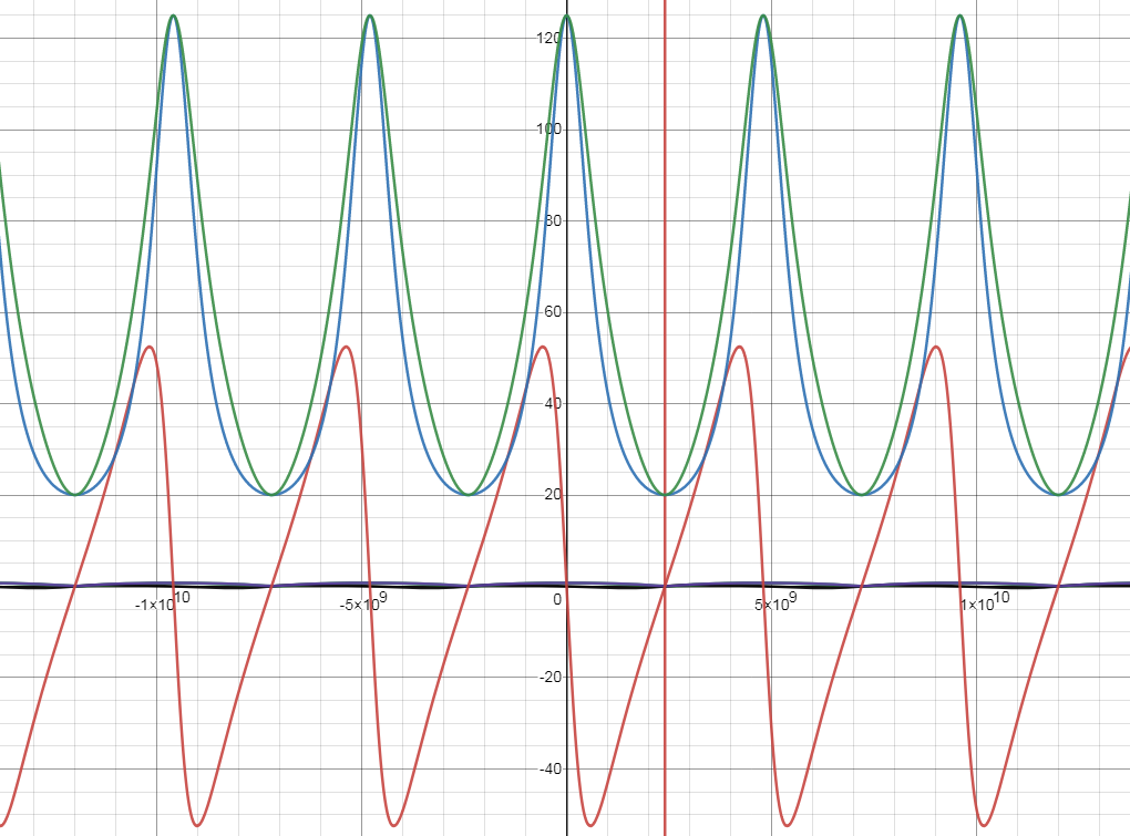
$$Z_{in}(f) = 50\frac{125+50i(\tan(2\pi f (\frac{1}{9600000000})))}{50+125i(\tan(2\pi f (\frac{1}{9600000000})))} $$
It is 20 ohms when it is matched i.e. at multiples of 2.4GHz
Here is a simulation of the quarter wave transformer piece of transmission line that I made (blue is voltage and red is current * 100):
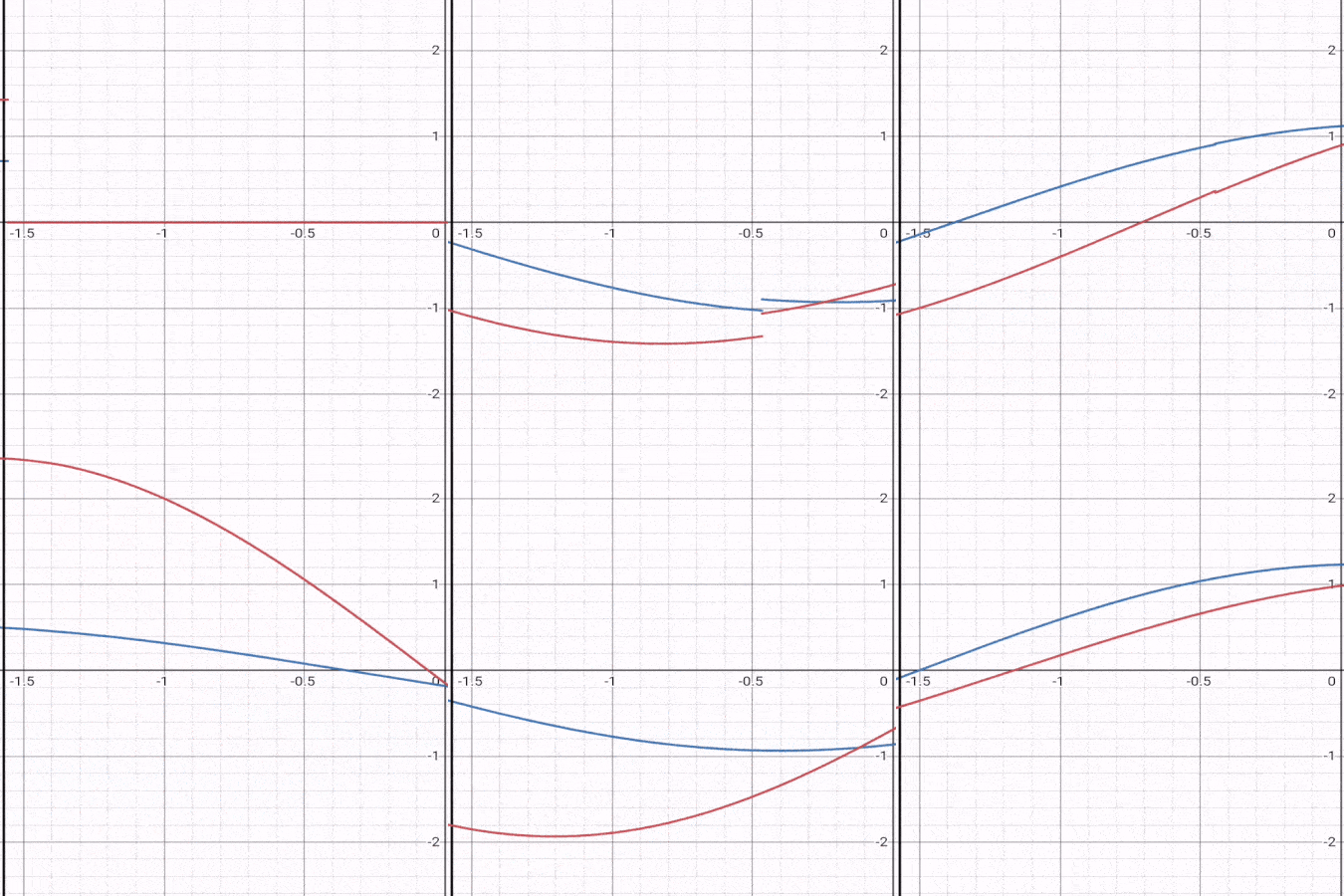
The source impedance is 20 ohms, the transmission line acting as the transformer is 50 ohms and the load 125 ohms. A sinusoid with an amplitude of 1V exudes from the generator. Initially 0.714285714V enters the transmission line due to the potential division between the source impedance and the characteristic impedance of the transformer. Similarly, 0.012485714A enters the transmission line. In the steady state, the source sees an amplitude of 0.5V and the load sees an amplitude of 1.25V. The power in the source is now matched to the load: ((0.5/sqrt(2))^2 / 20) W = ((1.25/sqrt(2))^2/125) W. The source therefore sees an amplitude of 0.025A and the load sees 0.01A. The power in the source and load is Vrms * Irms = 0.01/sqrt(2) * 1.25/sqrt(2) = 0.00625W. All amp readings have been multiplied by 100 so they are visible in the simulation. It is easy to see that power is in phase at the load and at the source, but if there is a mismatch, power at the load is always in phase, but at the source it has a reactive component.
Below is the frequency response of the quarter wave transformer measured at the output (red: real part of voltage frequency response; blue: imaginary part of voltage frequency response; dotted red: real part of current frequency response multiplied by 100 for scale; dotted blue: imaginary part of current frequency response multiplied by 100 for scale; orange: magnitude of voltage frequency repsonse; green: magnitude of current frequency response and then multiplied by 100 for scale; black: power delivered to load; dotted orange: phase of frequency response of voltage and power; purple: reflection coefficient magnitude frequency response; red line: x=2.4GHz)
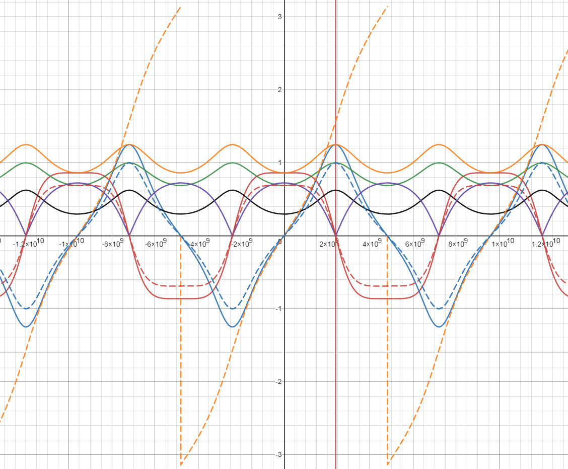
When it is matched, the response of this transformer is of course an imaginary 1.25, which represents a lag of 90 degrees (as it's quarter wavelength in length), and a magnitude of 1.25V, the voltage amplitude over the load that is needed to have the same power in the load as there is in the source (0.00625W). The magnitude of current is indeed an imaginary 0.01A, which gives 0.00625W in the equation Vrms*Irms. It can be seen that at the output, the voltage and the current are always in phase regardless of the frequency, which shows that it is always in phase regardless of length (so long as load and and source are resistive only).
The voltage impulse response (measured at the output) of the above quarter wave transformer for the wavelength of 2.4GHz is:
$$h\left(x\right)=\frac{50}{20+50}\lim_{T\to\infty}\left(\sum_{n=0}^{T}\left(\Gamma_s\Gamma_L\right)^{n}\left(1+\Gamma_L\right)\delta\left(t-\left(1+2n\right)\left(\frac{1}{4}\frac{1}{2.4GHz}\right)\right)\right)$$
The voltage frequency response show on the graph (measured at the output) is (the fourier transform of the above):
$$H\left(f\right)=\frac{50}{20+50}\lim_{F\to\infty}\left(\sum_{n=0}^{F}\left(\Gamma_s\Gamma_L\right)^{n}\left(1+\Gamma_L\right)\left(\cos\left(2\pi\left(1+2n\right)\left(\frac{1}{4}\frac{1}{2.4GHz}\right) f \right) + j\sin\left(2\pi\left(1+2n\right)\left(\frac{1}{4}\frac{1}{2.4GHz}\right) f \right)\right)\right)$$
The current frequency response shown on the graph is:
$$H_I\left(f\right)=\frac{1V}{20+50}\lim_{F\to\infty}\left(\sum_{n=0}^{F}\left((-\Gamma_s)(-\Gamma_L)\right)^{n}\left(1-\Gamma_L\right)\left(\cos\left(2\pi\left(1+2n\right)\left(\frac{1}{4}\frac{1}{2.4GHz}\right) f \right) + j\sin\left(2\pi\left(1+2n\right)\left(\frac{1}{4}\frac{1}{2.4GHz}\right) f \right)\right)\right)$$
The voltage phase response shown on the graph is (equal to current HI<\sub>(f) phase response in this instance):
$$∠H(f) = \arctan\left(\frac{\text{Im}\{H(f)\}}{\text{Re}\{H(f)\}}\right)+\text{sgn}(\text{Im} \{H(f)\})u(-\text{Re}\{H(f)\})\pi$$
Where u(f) is the heaviside step function.
The steady-state total reflection coefficient of the transformer shown on the graph is therefore
$$|\Gamma_{in}\left(f\right)|=\sqrt{\frac{\left(\frac{\left(\sup{(|H(f)|)}V_{in}\right)^{2}}{125}-\frac{\left(V_{in}|H\left(f\right)|\right)^{2}}{125}\right)}{\frac{\left(\sup{(|H(f)|)}V_{in}\right)^{2}}{125}}}$$
$$=\sqrt{\frac{\left(\frac{\left(1.75V_{in}\right)^{2}}{125}-\frac{\left(V_{in}|H\left(f\right)|\right)^{2}}{125}\right)}{\frac{\left(1.75V_{in}\right)^{2}}{125}}}$$
$$= \sqrt{1 - 0.326531 |H(f)|^2}$$
Here is the input frequency response of the transformer measured at the input (red: real part of voltage frequency response; blue: imaginary part of voltage frequency response; dotted red: real part of current frequency response multiplied by 100 for scale; dotted blue: imaginary part of current frequency response multiplied by 100 for scale; orange: magnitude of voltage frequency repsonse; green: magnitude of current frequency response and then multiplied by 100 for scale; dotted orange: phase of voltage response; dotted green: current phase response; black: apparent power at the transformer input (not instantaneous and not true power; purple: total phase difference between voltage and current)
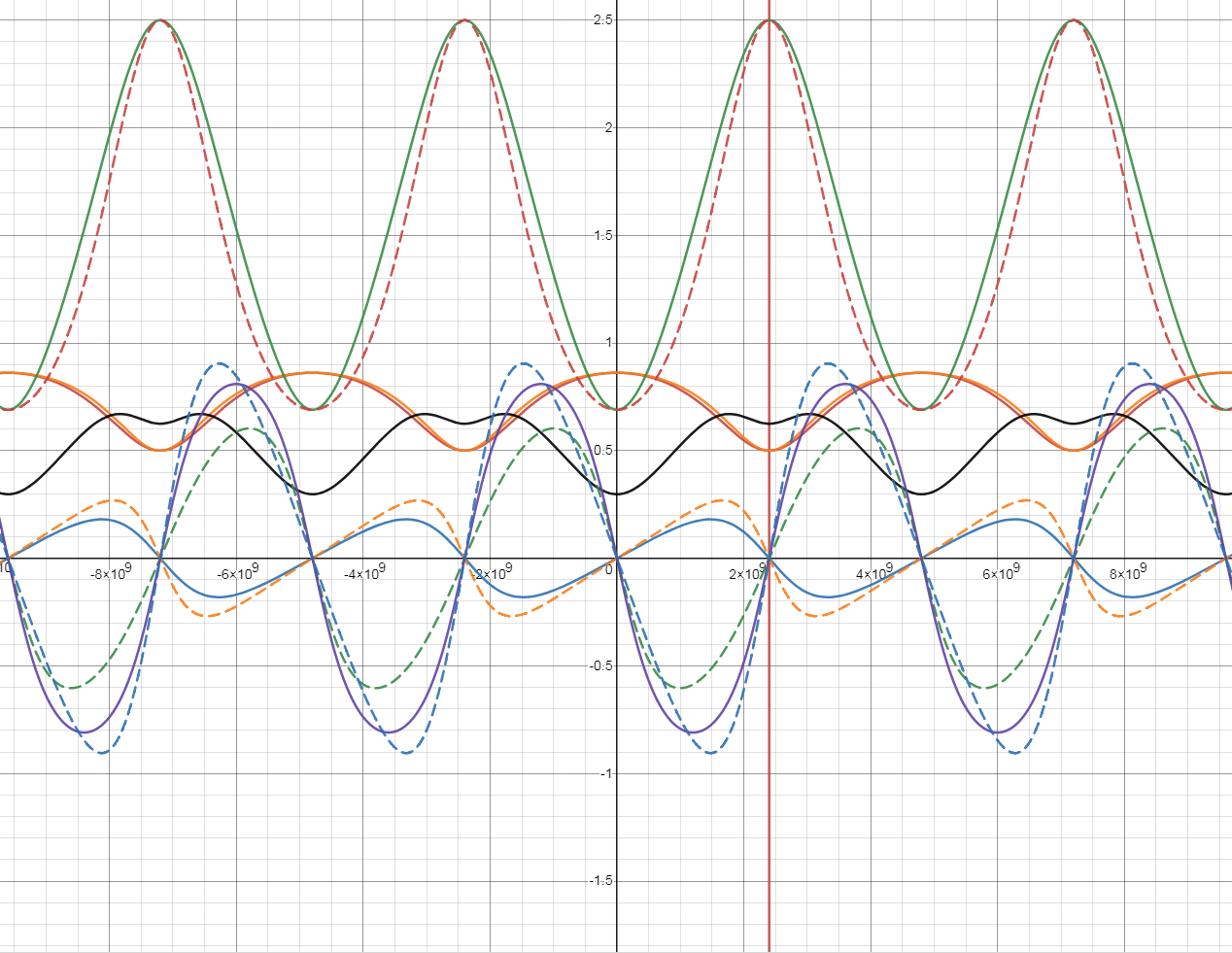
It can be seen that voltage and current are not in phase as their phase responses are different, even though source and load are resistive. The reflection coefficient at f=0 is 0.7421. 1.7421 * 0.5V = 0.8621, which is the input voltage mangnitude response at f=0.
The phase difference between the voltage and current phase responses at the input is indeed equivalent to the phase of the input impedance:
$$∠H_{Iin}(f) - ∠H_{in}(f) \equiv ∠Z_{in}(f) = \arctan\left(\frac{\text{Im}\{Z_{in}(f)\}}{\text{Re}\{Z_{in}(f)\}}\right)+\text{sgn}(\text{Im} \{Z_{in}(f)\})u(-\text{Re}\{Z_{in}(f)\})\pi$$
The input voltage frequency response shown on the graph is:
$$H_{in}\left(f\right)=\frac{50}{20+50}+\frac{50}{20+50}\lim_{F\to\infty}\left(\sum_{n=0}^{F}\Gamma_L^{n}\Gamma_s^{n-1}\left(1+\Gamma_s\right)\left(\cos\left(2\pi\left(2n\right)\left(\frac{1}{4}\frac{1}{2.4GHz}\right) f \right) + j\sin\left(2\pi\left(2n\right)\left(\frac{1}{4}\frac{1}{2.4GHz}\right) f \right)\right)\right)$$
The input current frequency response shown on the graph is:
$$H_{Iin}\left(f\right)=\frac{1V}{20+50}+\frac{1V}{20+50}\lim_{F\to\infty}\left(\sum_{n=0}^{F}(-\Gamma_L)^n(-\Gamma_s)^{n-1}\left(1-\Gamma_s\right)\left(\cos\left(2\pi\left(2n\right)\left(\frac{1}{4}\frac{1}{2.4GHz}\right) f \right) + j\sin\left(2\pi\left(2n\right)\left(\frac{1}{4}\frac{1}{2.4GHz}\right) f \right)\right)\right)$$
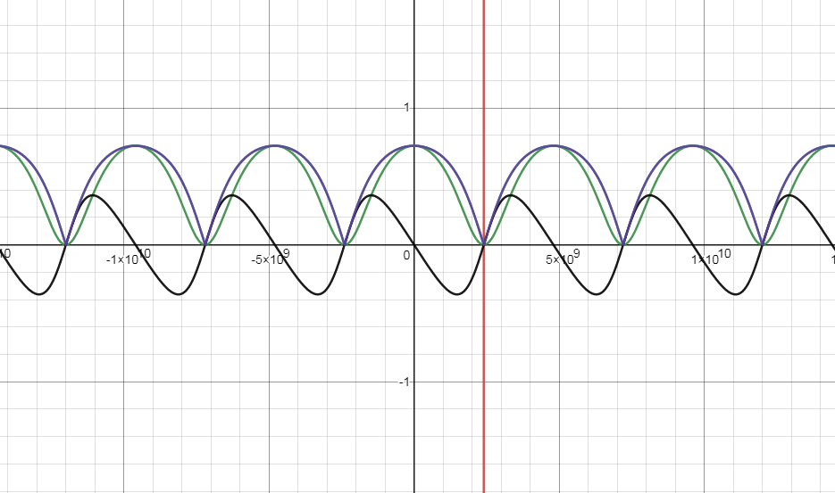
Here is the plot of the real (green) and imaginary (black) part of the reflection coefficient, and magnitude (blue) given by the source and input impedance equation:
$$ \Gamma_{in}(f) = \frac{Z_{in}(f) - Z_s}{Z_{in}(f) + Z_s} = \frac{Z_{in}(f) - 20}{Z_{in}(f) + 20} $$
In fact:
$$\sqrt{1 - 0.326531 |H(f)|^2} \equiv \left|\frac{Z_{in}(f) - Z_s}{Z_{in}(f) + Z_s}\right| $$
Remember this is all for a perfect transformer as opposed to a lossy one
Using a quarter wave transformer between a source and a load is the same as using it between a transmission line (that's matched to a source) and a load, and in the equilibrium state will be transferring 100% of the power to the load which is V²/4Rsource. The potential division between the source and the characteristic impedance of the transformer plus the reflection off the load is identical to the potential division between the source and the characterstic impedance of the transmission line (so long as they have the same impedance), plus the reflection off the quarter wave transformer plus the reflection off the load.


