0
\$\begingroup\$

Goal
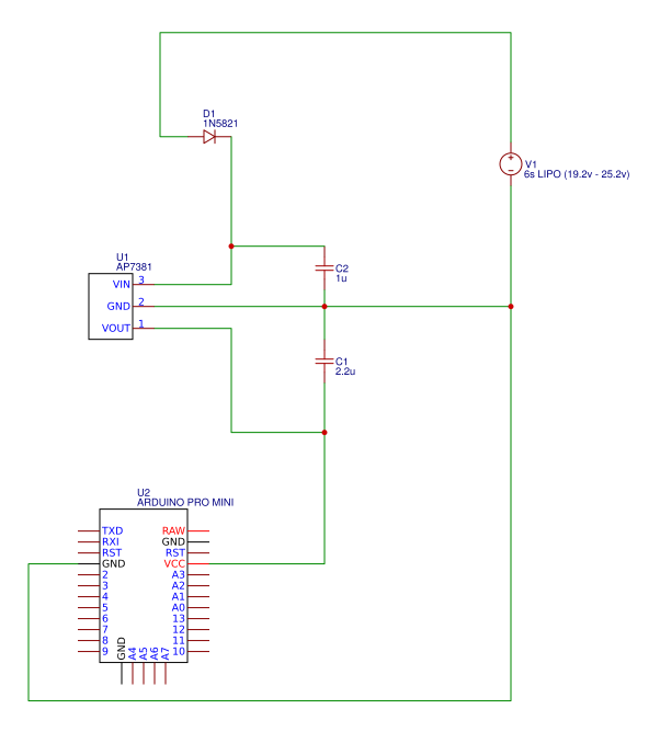
I'm trying to build a portable speaker. I want to use an arduino to handle several tasks. The speaker uses a 6s Lipo ~24v as power source. An LDO the AP7381 has been selected as power source for the arduino.

The AP7381 provides the required 5V on a wide input range while having a low quiescent current which is important for the battery life. The idea is to have a very low power consumption when the speaker is off and the arduino sleeping drawing less than 10uA.

I want to test the power source with the arduino before I blow up multiple components.

The datasheet of the AP7381 recommends to use a 1uF input and a 2.2uF output capacitor. I use ceramic capacitors.

Problem
The isolated test for the power source of the arduino has failed several times now with a destroyed LDO but I cannot see the problem in my schematic.

(I suspected reverse current on the LDO to be a problem which is why I added the diode but it didn't help.)

I have tried the following:
- Using a step down converter -> works
- Using the AP7381 without capacitors -> works (not a good idea I guess)
- Using a diode to prevent reverse current (as seen on the schematic) -> fails
- Using no diode -> fails

What could cause the LDO to blow in this small setup?

AP7381 datasheet: link
Diode datasheet: link

schematic

\$\endgroup\$
8
  • 2
    \$\begingroup\$ You are using a linear regulator to drop 24V to 5V. This is practically the definition of "inefficient." The quiescent current doesn't even begin to be a problem. \$\endgroup\$
    – JRE
    Commented Jul 18, 2019 at 11:14
  • \$\begingroup\$ The arduino will mostly be in a sleeping state where it should draw few uA only, I thought this to be more efficient because of this. Would it be better to use a stepdown converter? But I would need one drawing less than 100uA. \$\endgroup\$
    – einfach3
    Commented Jul 18, 2019 at 11:17
  • \$\begingroup\$ Assume the Arduino draws 100mA. Dropping 19V at 100mA wastes 1.9W of power - while the Arduino consumes only 0.5W of power. You are wasting 4 times as much as you are using. \$\endgroup\$
    – JRE
    Commented Jul 18, 2019 at 11:17
  • \$\begingroup\$ 1.9W waste of power is not a problem for me when the speaker is on and using up to 50W. My focus is on having a very low power consumption when the arduino sleeps and the speaker is off. I updated the question to include this. \$\endgroup\$
    – einfach3
    Commented Jul 18, 2019 at 11:23
  • 1
    \$\begingroup\$ If adding a diode makes it fail (for which there is no reasonable explanation), I'm inclined to think your real connection don't match the schematic. \$\endgroup\$ Commented Jul 18, 2019 at 11:49

1 Answer 1

-2
\$\begingroup\$

Depending on the actual package for your regulator, the total power dissipation will be limited to something less than a watt. Trying to dissipate more power than this in the regulator will cause it to overheat. To be on the safe side, you should probably limit the power to about 0.5W.

So with 19V across the regulator you don't want to draw more than about 25mA. Your Arduino is probably drawing much more than that, particularly if you are connecting any loads to the output pins.

Your best option is probably to use a dc-dc converter instead of a linear regulator. If you insist on using a linear regulator, you could select one that can dissipate more power...even an ancient 7805 in a TO220 package would be better.

\$\endgroup\$
4
  • \$\begingroup\$ The limit of less than a watt should be achievable. The arduino including two INA219 sensors and a oled display draw about 23mA (12mA + 2*1mA + 9mA). \$\endgroup\$
    – einfach3
    Commented Jul 18, 2019 at 11:44
  • \$\begingroup\$ Is a dc-dc converter able to handle very low current draw (less than 10uA) more or less efficiently compared to the linear regulator? I fear the battery being drained in a few weeks when the speaker is turned off and the arduino sleeping. \$\endgroup\$
    – einfach3
    Commented Jul 18, 2019 at 11:46
  • \$\begingroup\$ Now you are asking a question about system design rather than failure modes of a linear regulator. You need to do a detailed analysis of power consumption of all elements (where did this speaker come from?) and specify the expected usage scenario. There is no blanket answer for this. \$\endgroup\$ Commented Jul 18, 2019 at 12:01
  • \$\begingroup\$ The speaker is not powered from the regulator and therefore should not matter for this isolated test. My questions is limited to powering the arduino only - but in two situations: When powered on (drawing about 12mA) and when sleeping (drawing less than 10uA). But until now the regulator always blows when connecting it to the battery but I cannot see why. \$\endgroup\$
    – einfach3
    Commented Jul 18, 2019 at 12:13

Your Answer

By clicking “Post Your Answer”, you agree to our terms of service and acknowledge you have read our privacy policy.

Not the answer you're looking for? Browse other questions tagged or ask your own question.