1
\$\begingroup\$

Diagram

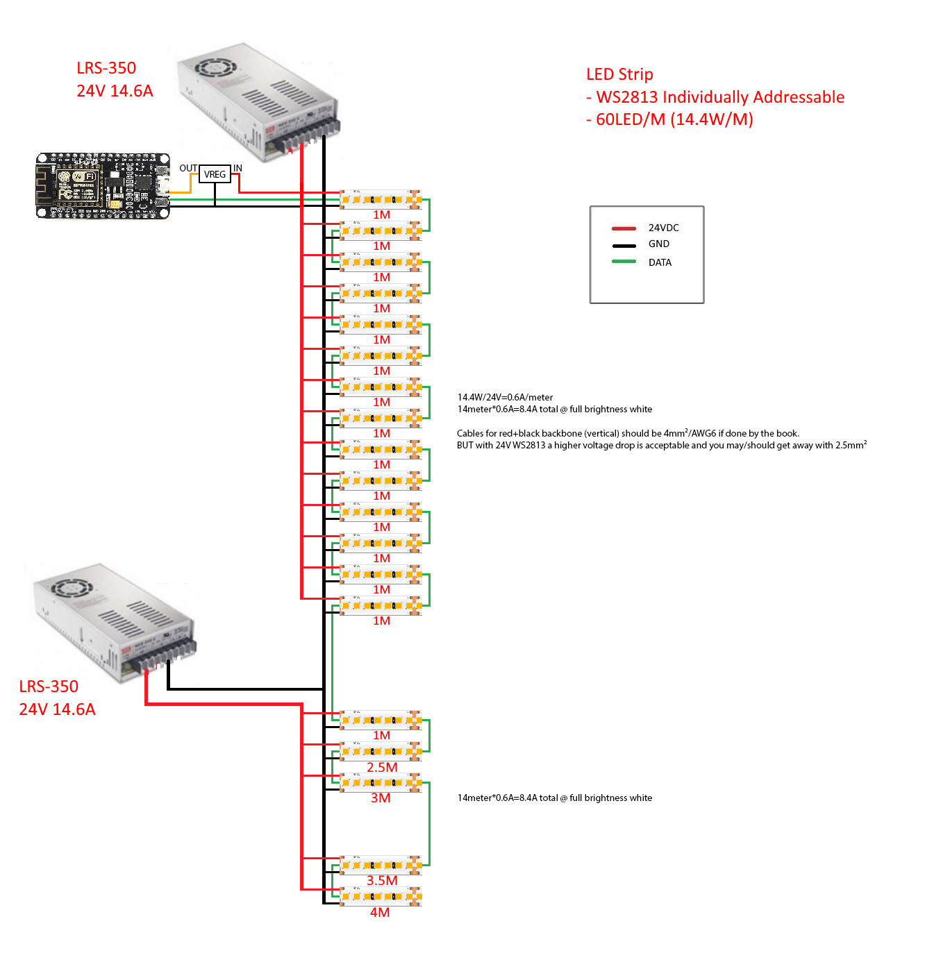
Please refer to the above diagram.

The 2 power supplies are each placed in the opposite end of the led strip.

I will be connecting the signal ground and the power ground just before it connects to the led strip to reduce noise.

But do I need to tie the grounds of the 2 power supplies? I searched around and it seems I do indeed need to until I came across this thread:

Can identical DC power supplies with common ground produce varying voltage on same circuit?

RoyC said, "The better one has the horizontal ground line just below the supplies removed and the ground from each extra supply connected directly to the strip it is driving as well as the ground from the driver board".

I may have mistaken the meaning of his statement but does that mean I have to connect the grounds of the 2 power supplies right before the load and not right after the power source as seen by the orange line drawn in the diagram?

But the length between the start and the end of the strip is around 13M and the distance between each strip is different (strip 1 and strip 2 distance is around 11M while strip 2 to strip 3 is 1M). Does that change anything?

\$\endgroup\$
4
  • \$\begingroup\$ Draw a resistor network with the cables and LEDs with distributed R and compute your losses. All cables will have voltage drop.so you want to minimize the logic ground shift and overall supply drop. \$\endgroup\$
    – D.A.S.
    Commented Jul 22, 2019 at 8:28
  • 1
    \$\begingroup\$ There's no issue with voltage drop that will affect the signal. I am more concerned with whether is it correct to tie the grounds as per the orange line? \$\endgroup\$
    – HA E
    Commented Jul 22, 2019 at 8:39
  • \$\begingroup\$ Your picture makes no sense and imparts no information. It is your artistic impression of things but in effect, it is a cartoon of some idea that is hidden. Draw a proper schematic and include links to data sheets and an explanation of why you believe you need two power supplies. \$\endgroup\$
    – Andy aka
    Commented Jul 22, 2019 at 9:00
  • 1
    \$\begingroup\$ Read my comment again and do that. All grounds are defined as 0V, so they are common but when floating and connected in series, there is a voltage drop with current flow \$\endgroup\$
    – D.A.S.
    Commented Jul 22, 2019 at 19:32

1 Answer 1

1
\$\begingroup\$

There is no need to tie ground as per the orange line, in fact it can be detrimental as you are effectively creating a long ground loop.

To understand exactly what is going on you should design and simulate your circuit with small resistors on both ground and power between each LED, like others have suggested.

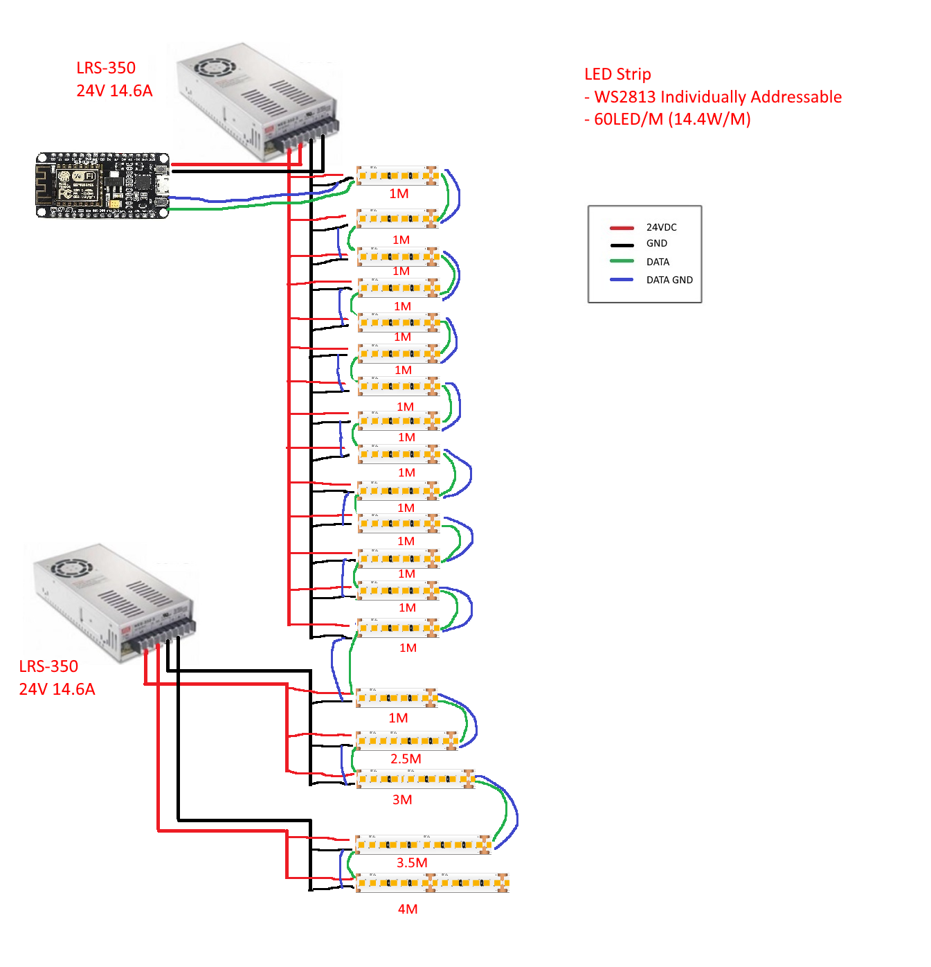
Edit after changes to question 22/7:

I would recommend you connect the system as follows:

Recommendation

\$\endgroup\$
9
  • \$\begingroup\$ Why would setting the reference to all sources to be the same be detrimental? To tie them all is done precisely to avoid ground loops as far as I'm aware. \$\endgroup\$
    – lucasgcb
    Commented Jul 22, 2019 at 10:49
  • \$\begingroup\$ I am asking because i want to know the correct way to wire - the wires are going into conduits that will be buried in a concrete wall - so i want to be 100% sure that there will be no problems because i can't add any wire afterwards due to the bends etc. With due respect, may i know the answer to lucasgcb's question as well? As i have read on many sites that the grounds between multiple power supplies powering the same strip need to be tied - they advise doing "star ground" for high current which i have exactly no idea what it is due to my very limited knowledge and hence the question. \$\endgroup\$
    – HA E
    Commented Jul 22, 2019 at 12:18
  • \$\begingroup\$ @lucasgcb There is already a ground wire in the LED strip. Adding another one creates a ground loop. Ground loops and why they are detrimental is too big of a subject to cover in a comment. While haphazardly adding ground at various locations is certainly equivalent to "tying them down" as far as DC is concerned, not so much at higher frequencies. F.ex: just 30m of ground loop will amplify signals at ~10Mhz and may even resonate, being constantly stimulated by switching noise from the LEDs. The LEDs input circuitry is sensitive to these frequencies. \$\endgroup\$ Commented Jul 22, 2019 at 12:38
  • \$\begingroup\$ @RonaldMcFüglethorn This really leads back to OP's artistic depiction of his circuit. I feel we may be confusing Ground with Reference. \$\endgroup\$
    – lucasgcb
    Commented Jul 22, 2019 at 13:01
  • 1
    \$\begingroup\$ @HAE Star ground is what you want. Avoid loops and you will be good. That said, I think you should connect everything up and test it before installing, just to verify your solution. You should also always have a way of replacing the LED strips if they fail - that is don't build them in such that replacing them becomes impossible. They do have a limited lifetime and it is not uncommon to see them fail prematurely, especially cheaper ones and even more so if installed outdoors/on material that expands /w heat. I've seen strips fail after just weeks, but also last up to four years (and counting). \$\endgroup\$ Commented Jul 22, 2019 at 14:09

Your Answer

By clicking “Post Your Answer”, you agree to our terms of service and acknowledge you have read our privacy policy.

Not the answer you're looking for? Browse other questions tagged or ask your own question.