1
\$\begingroup\$

Circuit primitive in CircuitJS

First, I'm having a hard time with transistors, and only recently managed to pass current through a NPN as planned (70-ish mA from 5 V with a 325 hFE 2N3904 with a 10K Ohms to the base).

Second, I'm using a ESP8266 devboard, which can only pass 40-ish mA through its GPIO pins, and a Songle relay that needs 70 mA at the coil according to the specs.

I have 3.3 V from my breadboard power supply going to the rail, then to the MCU Vin, and again from the rail to the relay's coil, and the other side of the coil to the NPN's collector; the emitter is connected to the ground rail, as is the MCU. The base is connected to a GPIO, via a 10K resistor; the hFE is 325.

Everything is powered from the same battery, so is at the same potential (I used to try while the MCU was connected to USB, but I wasn't sure if this was a problem or not).

I cannot get the relay to click, or even a LED to light.

If someone could walk me through the math, and tell me what I'm doing wrong, I'd greatly appreciate. Transistors were pushed to me as "simple", and "like a switch", but it's neither to me, and the simple fact there's also PNP transistors kinda makes me want to cry.

Again, any help would be dearly appreciated. I would post a picture of the setup, but there's a lot of stuff on the breadboard, and I'm not sure it'd be clear, but do let me know if it would be necessary.

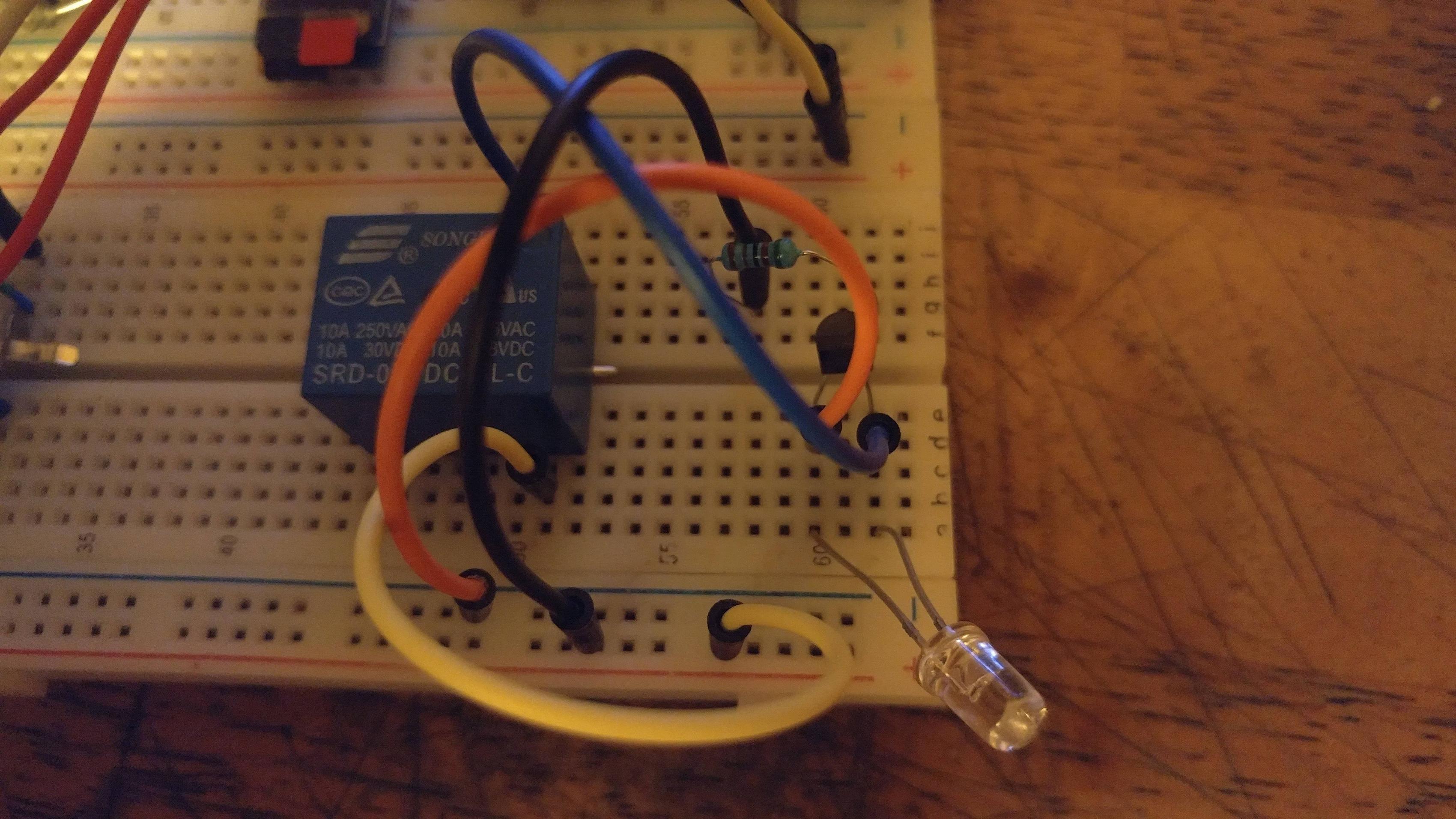
[Picture added]

Circuit on breadboard.

\$\endgroup\$
7
  • 1
    \$\begingroup\$ What is the specified coil voltage of the relay? You probably need a much lower value resistor on the base - try 2K (and measure the voltage between emitter and collector of the transistor - it should be under 0.3 volts if the transistor is saturated. \$\endgroup\$ Commented Jul 27, 2019 at 0:44
  • \$\begingroup\$ There are PCB mount relays that draw only 12 to 30 ma at the coil. A 70 madc coil would be for a large relay. What are your relay requirements? \$\endgroup\$
    – user105652
    Commented Jul 27, 2019 at 1:47
  • \$\begingroup\$ @PeterBennett It's almost certainly a \$5\:\text{V}\$ relay. These are often \$70\:\Omega\$ devices. Of course, relays vary. So that's granted. \$\endgroup\$
    – jonk
    Commented Jul 27, 2019 at 7:24
  • \$\begingroup\$ PNP and NPN transistors, as switches, aren't too difficult to parse. As a switch, both types of BJT "pull" their collector towards their emitter voltage, when active. (On.) You use an NPN when you want to pull its collector "downward" towards its emitter -- likely tied to the lower voltage reference (or ground.) You use a PNP when you want to pull its collector "upwards" towards its emitter -- likely tied to the higher voltage value (such as \$5\:\text{V}\$.) NPNs "pull down" and PNPs "pull up." If your switch is between the load and the more negative rail, use an NPN. Otherwise, a PNP. \$\endgroup\$
    – jonk
    Commented Jul 27, 2019 at 7:29
  • \$\begingroup\$ @PeterBennett : I've added a picture... If connected to the 3.3V rail, the relay clicks... I only had a 5K resistor on the bench, and my E-C voltage is 0.14V. Connected as you see, nothing's happening, and the BJT's cold... : [ \$\endgroup\$ Commented Jul 29, 2019 at 3:02

3 Answers 3

2
\$\begingroup\$

I had same problem too.

First assume your coil needs 100ma to click. Then your hfe is 325 which is the amplification factor in common base mode. That is the current from your base will be 325 times smaller than the current from your collector. You told you gave 10k resistor in between them. Assuming that esp is running exactly at 3.3v and the voltage drop across the base to emitter is 0.7v we get a potential drop of 2.6v across the resistor. This led to a base current of 2.6/10000 = 0.25mA. This will result in a collector current of 0.25*325 = 81mA. Which is barely enough for the required specs.

You can either use s a transistor with higher hfe or lower the resistor down to 6.4k or 5.6k then it will work.

\$\endgroup\$
1
\$\begingroup\$

After a while, and no more answers, I carefully inventoried all my transistors, and picked a transistor which's tolerances were closer to what was required of it, and it worked... It managed to pass all the current the coil needed, and the relay clicked. I was very happy, but I still couldn't understand why this transistor worked, and why the other one didn't... What was really bugging me was that, besides the "amplification", there were no settings in my circuit simulator, which is otherwise pretty complete, and it would've surprised me if there had been other significant parameters for the transistor...

I decided to replace the new transistor in the circuit with the old one, just to see if it'd work, and indeed, the relay clicked.

The problem was that, besides the base being saturated, my N23904 transistor wasn't letting more than 40-ish mA through, which wasn't enough to quench the 70-ish nA the coil needed (as per spec), but if I just connected the coil on the 3.3 V line, it clicked just fine, and enough current could flow. That was the problem. But now the problem was gone... The relay was clicking just fine...

I'm still not sure what the problem was, maybe there's a difference I'm not seeing between what's in the picture, and my re-wired circuit; maybe there was a bad connection, maybe one of the terminals was oxidized, and the resistance wouldn't allow more than 40 mA on 3.3 V; maybe my understanding just wasn't good enough to make it work, and it still isn't good enough to be able to tell what was wrong, ... Whatever the case may be, it works now, and I understand transistors a bit better than I did, and I'm going to keep in mind that maybe it was a connection problem, and see if maybe I don't need a new breadboard or something... I kinda wish I had measured the resistance now, but it's too late for that.

At any rate, thanks again to those who tried to help, and I am still glad to be part of the community.

Cheers,

\$\endgroup\$
6
  • \$\begingroup\$ Actually I think it's the coil... It only works if I flick the switch a few times after I disconnect it for a while, once the coil flicks the switch, the holding torque is only about 35 mA... This is my first experience with a coil, and I have to say, my mind is a bit blown.... I don't have an inductance meter, but this is freakin' awesome, even if it doesn't quite solve my problem... \$\endgroup\$ Commented Aug 7, 2019 at 20:39
  • \$\begingroup\$ You can't reliably run a 5 V relay on a 3.3 V supply. It probably just picks up at 3.3 V but with the extra voltage drop across the transistor there isn't enough to energise it. "35 mA" is a measure of current, not torque, but I think we know what you mean. \$\endgroup\$
    – Transistor
    Commented Aug 7, 2019 at 21:51
  • \$\begingroup\$ @Transistor : Why can't I reliably activate a 5 V relay on a 3.3 V supply? The 70 ohms coil draws 65 mA at 5 V and about 40 at 3.3. I can tell you without any doubt that the force needed to overcome the inertia of the contact is a lot greater than the force required to maintain that contact in place... not only is it a lot closer to the magnet's pole, it's also already there, and we're talking a low current, so the short distance goes a long way... If I can get it reliably moving, which I can't right now, but probably would be able to do with a voltage regulator or some analog magic (1/2) \$\endgroup\$ Commented Aug 10, 2019 at 18:07
  • \$\begingroup\$ (2/2) I'm pretty sure I can get the coil to move reliably. Besides, this is a learning, learning, and discovery exercise, and it has no practical application, and certainly none that's critical at this time. The exercise to play with my components, and math, and try to be creative and find out a way to make it work is invaluable. Because the specs tell you not to doesn't make it so you can't. I'm not going to sue myself, and if I return the product from my kitchen to my desk, that's no logistical nightmare... Also, who the hell are you to speak for everyone who have, or will read this? \$\endgroup\$ Commented Aug 10, 2019 at 18:13
  • 2
    \$\begingroup\$ "... who the hell are you to speak for everyone who have, or will read this?" I treated you with respect. Goodbye. \$\endgroup\$
    – Transistor
    Commented Aug 10, 2019 at 19:54
1
\$\begingroup\$

It would be a good idea to add a flyback diode around the relay coil. Also you should probably have some margin in your base current. For example, if you need 100ma CE current with a hfe of 325, that means you need a min of 307ua in the base, so I would shoot for 400 or 500ua. Some people just look at the curve for the transistor and dump a load of current in the base to force the transistor into saturation no matter what.

\$\endgroup\$

Your Answer

By clicking “Post Your Answer”, you agree to our terms of service and acknowledge you have read our privacy policy.

Not the answer you're looking for? Browse other questions tagged or ask your own question.