2
\$\begingroup\$

I am trying to design af system using the XUF-208-256-TQ64 Xmos controller (https://www.xmos.com/download/XUF208-256-TQ64-Datasheet(1.16).pdf). The system should get an audio stream from USB, upsample and then output the stream as an I2S signal.

It is my first time designing a PCB for digital signals.

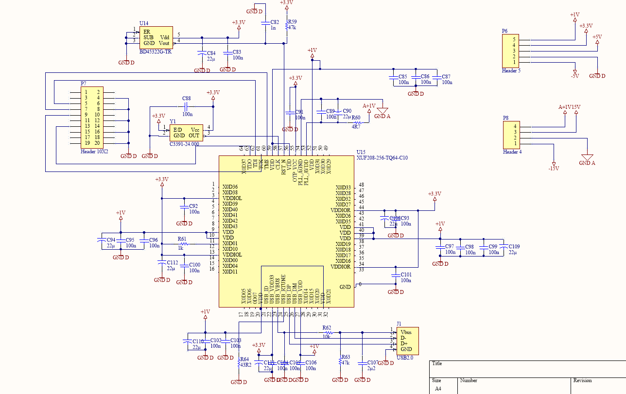
The schematic for the xmos implementation:

enter image description here

Y1 is a 24 MHz oscillator. Datasheet: https://www.mouser.dk/datasheet/2/94/C33xx-186.pdf

U14 is a voltage detector with time delay, for holding reset at startup. Datasheet: https://www.mouser.dk/datasheet/2/348/bd45xxg-e-746184.pdf

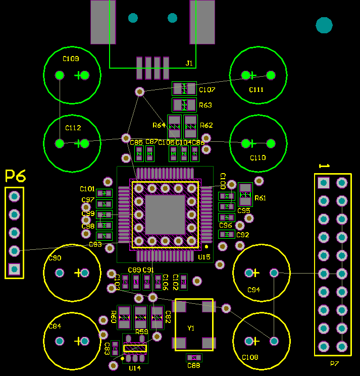
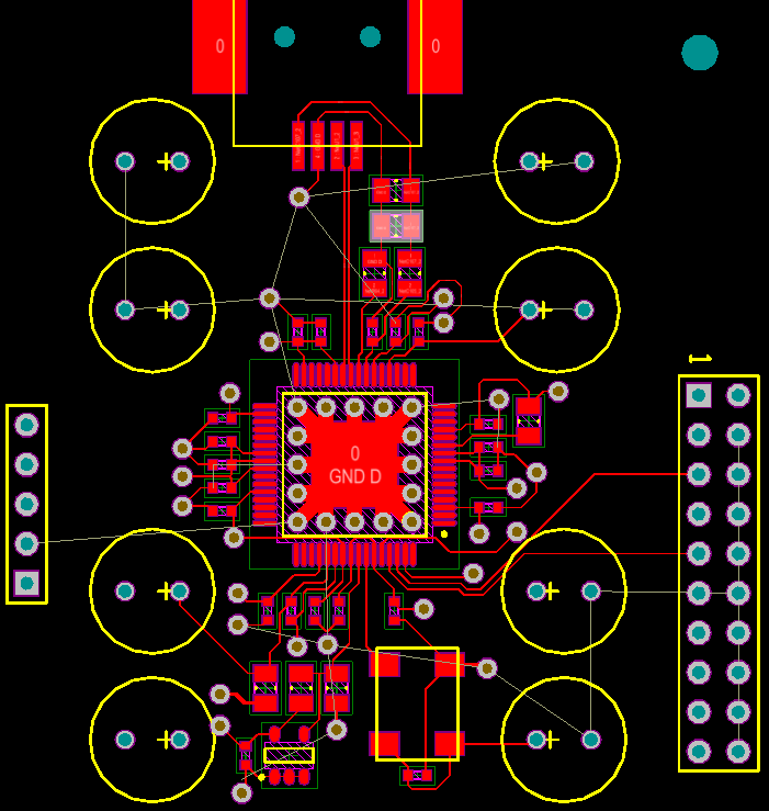
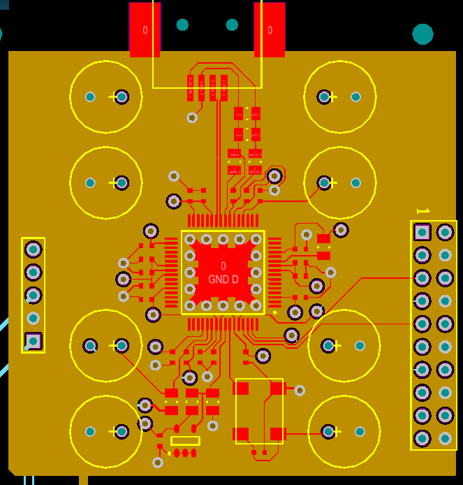
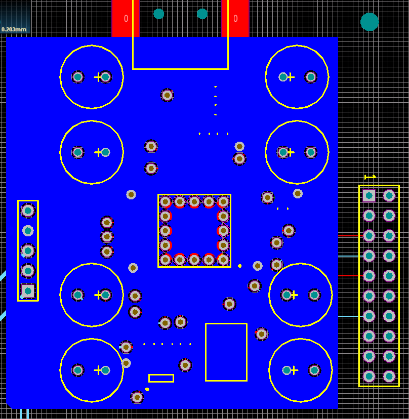
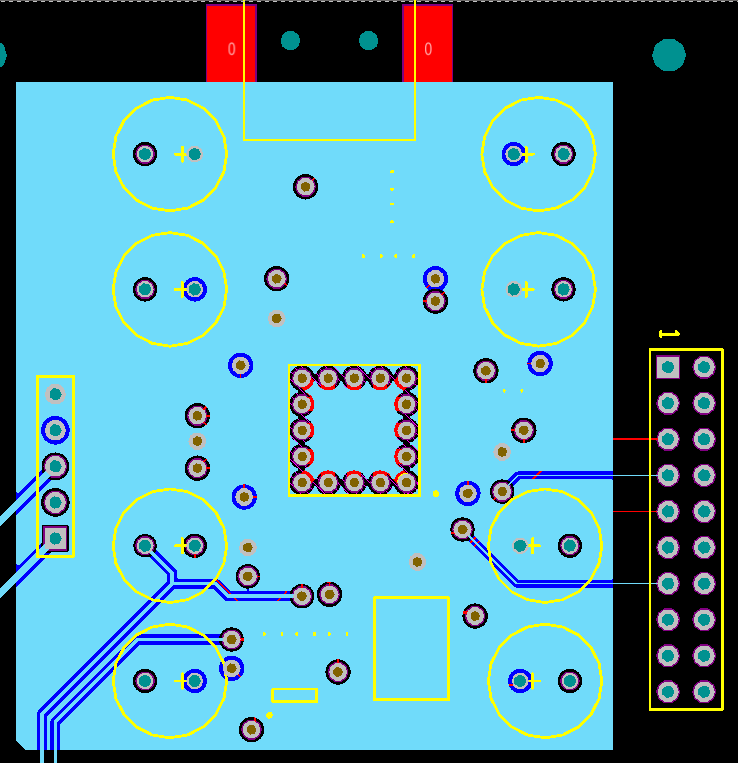
I am laying out a 4-layer PCB, and would like some comments if I have done something that might not work + some specific questions. The PCB looks like this:

No layers, just components: enter image description here

Signal layer: enter image description here

Ground plane: enter image description here

3.3 V supply plane: enter image description here

1 V supply plane: enter image description here

My questions are:

1) On the datasheet for the Xmos it says that ecoupling capacitors should be as close to the IC as possible. How close would a minimum be? I have put the capacitors as close as I can, with tracks coming out, will this be enough?

2) On the datasheet for the Xmos it says that the USB-standard dictates a differential impedance of 90 Ohm between the lanes. I find it hard to find information on this, and I have not found any specific implementations of this. What is to be done, to have this, and is it even needed? Is it implemented in the IC?

3) On P. 72 the datasheet says that RST_N should be fast enough for USB timing. But RST_N is just a signal to hold the IC in reset, what does this have to do with USB timing?

4) The datasheet states that the clock signal should rise/fall monotonic. However I do not find this in this datasheet for oscillators. Should I just assume that the oscillator is usable?

5) Should the tracks for the xsys header be same length? The datasheet do not say anything about this.

6) The datasheet says that I should minimize the amount of vias around the IC. Do I have too many, and how could it be done differently? By using longer tracks to the surface mounted components?

7) The PLL filter should, according to the datasheet, be as close to the IC as possible. Is my filter close enough? This is basically the same as question 1, but is the requirements the same?

I know this is a lot. I have tried to read the datasheet as good as possible, but these questions still stands. I hope some of them may be answered.

\$\endgroup\$
1
  • 1
    \$\begingroup\$ Some general notes: 1. The large vias under the chip are going to suck away all of the solder, suggest not using them or plugging first. 2. Thermal relief should be added to electrolytic cap pads, otherwise they are going to be a nightmare to solder. 3. Traces for power and decoupling caps in particular should be wider. \$\endgroup\$
    – rdtsc
    Commented Jul 29, 2019 at 16:18

1 Answer 1

1
\$\begingroup\$

On the datasheet for the Xmos it says that ecoupling capacitors should be as close to the IC as possible. How close would a minimum be? I have put the capacitors as close as I can, with tracks coming out, will this be enough?

It's the parasitic inductance that creates problems between the caps. You can either calculate the trace inductance and resistance (with a PCB calculator) and calculate how it affects the bypassing of the cap. Or just place the caps as close as possible. For most applications, under 50mil is fine.

3) On P. 72 the datasheet says that RST_N should be fast enough for USB timing. But RST_N is just a signal to hold the IC in reset, what does this have to do with USB timing?

They probably mean the reset is fast enough when powered from USB that the processor will be ready because the reset is short enough.

4) The datasheet states that the clock signal should rise/fall monotonic. However I do not find this in this datasheet for oscillators. Should I just assume that the oscillator is usable?

This means the clock signal, once the clock signal starts moving it should go straight down or straight up. If the signal does not (is noisy or has weird harmonics) this could lead to digial logic problems or problems with the PLL if the IC has one. It should look like a clean clock signal.

On the datasheet for the Xmos it says that the USB-standard dictates a differential impedance of 90 Ohm between the lanes. I find it hard to find information on this, and I have not found any specific implementations of this. What is to be done, to have this, and is it even needed? Is it implemented in the IC?

My personal favorite calculator for differential traces is Saturn PCB toolikit. Another tools is found here. Differential traces are simply transmission lines so you may want to brush up on transmission line theory if you haven't done so. Lines need to be matched to reduce attenuation\reflection.

5) Should the tracks for the xsys header be same length? The datasheet do not say anything about this.

I don't see anything labeled as XSYS on your schematic
If they are not impedance controlled or run under 50Mhz then I would say no.

6) The datasheet says that I should minimize the amount of vias around the IC. Do I have too many, and how could it be done differently? By using longer tracks to the surface mounted components?

Depending on the signal it can be bad to run signals through many vias. The design looks fine. You may want to consider using smaller vias (check your PCB manufacturer to see what they support)

7) The PLL filter should, according to the datasheet, be as close to the IC as possible. Is my filter close enough? This is basically the same as question 1, but is the requirements the same?

I would be more concerned about the PLL ESL, you could probably rotate C89 and move some other components out of the way to get it closer.

\$\endgroup\$

Your Answer

By clicking “Post Your Answer”, you agree to our terms of service and acknowledge you have read our privacy policy.

Not the answer you're looking for? Browse other questions tagged or ask your own question.