3
\$\begingroup\$

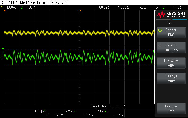
I'm having a very odd issue using an integrated DC-DC isolated converter module. As the module stabilizes, a massive pk-pk ripple is developing on both the output and the input. At first we thought this might be induced by characteristics of the circuit it was supplying or its own supply, but even after completely removing the module and simply using it to drive a resistive load we are still seeing this symptom. To be clear, the module does output exactly an average 4.995VDC given a 48VDC supply, but the ripple is 1.29V pk-pk! Has anyone else seen this behavior before that might be able to offer some clues? Scope shots and details below:

DC-DC Module

  • PN: SHHD003A0A Datasheet
  • Mfg: ABB Embedded Power
  • Input Range: (4:1) 18-75 VDC
  • Output: 5 VDC / 3A

Test Setup

  • DC-DC alone on a perf-board with oscilloscope prove connected across VOut+/VOut-
  • BK Precision supply providing 48VDC to VIn+/VIn-
  • Trim and Remote ON/OFF disconnected (open circuit)
  • 1kOhm Resistor across VOut+/VOut- as "load"

This is a scope shot from VOut-. Pk-pk noise is 1.29V. The periodicity of the transient exactly matches the switching frequency of the DC-DC.

VOut-

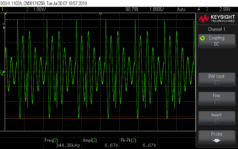
This is a shot from VIn- where a similar transient is observed 6.67V pk-pk noise!

VIn-

UPDATE 1

-- Removed for simplicity --

UPDATE 2

To take our particular application circuit out of the equation, this is the test setup I am using (constructed using the shortest possible soldered connections on a perf-board):

Testbed

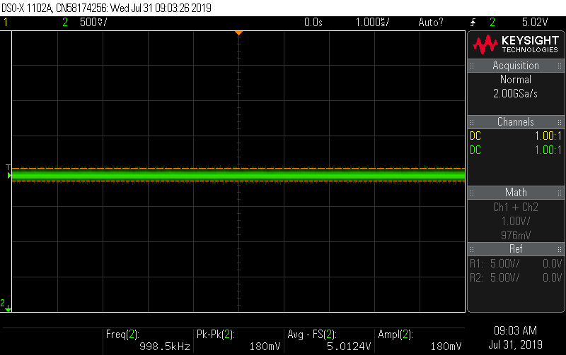
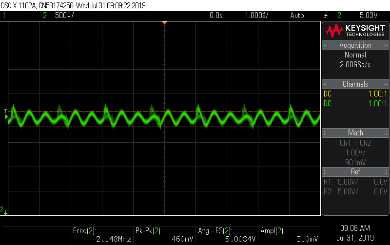
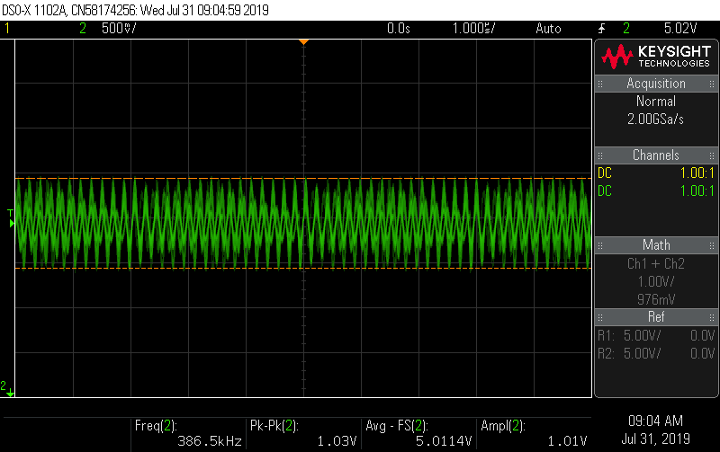
There seem to be two issues contributing. One is the bench-top power supply being used which itself introduces significant ripple. Second is defeating the DC-DC converter's isolation by shorting VIn- and VOut- together. The three images show each condition. Even the 180 mV pk-pk noise in the best case (powered by battery), while potentially acceptable in the application, is double the datasheet specification (75 mV)!

It just gets worse from there. Ripple is 460 mV pk-pk when the DC-DC is powered by a bench-top supply (with identical results from several other switching AC-DC converters I had lying around). Finally, ripple worsens to 1030 mV pk-pk if VIn- and VOut- are shorted to defeat isolation and bring input and output ground to the same reference (while powered via battery). What's going on here, is it possible this is just a marginally stable poorly designed DC-DC module?

Powered by battery, maintaining isolation: Battery power with isolation
Powered by BK precision bench-top supply, maintaining isolation: Benchtop power with isolation
Powered by battery, with isolation broken using an 18awg wire short directly from VIn- to VOut-: Benchtop power no isolation
\$\endgroup\$
14
  • 1
    \$\begingroup\$ Try powering it off two or three 9V batteries and see what happens. Or a linear supply. Or just a different type of switching supply. \$\endgroup\$
    – DKNguyen
    Commented Jul 30, 2019 at 18:28
  • 2
    \$\begingroup\$ The first thing to ask yourself when probing with an oscilloscope is: where is the ground located? and Is it the right ground? and How good is my ground? \$\endgroup\$
    – Voltage Spike
    Commented Jul 30, 2019 at 18:32
  • 1
    \$\begingroup\$ As @VoltageSpike is hinting, once you connect a 'scope probe to a circuit you (usually) no longer have isolation from ground. Strange things can happen. What do you see if you make ac and dc voltage measurements with a battery-operated meter? \$\endgroup\$ Commented Jul 30, 2019 at 18:54
  • 1
    \$\begingroup\$ Another possibility is that the supply has an output filter. An output filter feeding a DC-DC (negative incremental input impedance) can cause instability and the kind of behavior you're seeing. Google "Middlebrook criterion". You could also try a big bulk cap right at the input to the module to see if that fixes it. \$\endgroup\$
    – John D
    Commented Jul 30, 2019 at 19:09
  • 1
    \$\begingroup\$ Did you add a 33uF capacitor on the input, as suggested in page 6 of the datasheet? \$\endgroup\$
    – BeB00
    Commented Jul 30, 2019 at 19:17

1 Answer 1

1
\$\begingroup\$

It's been some time since I opened this question but I wanted to share the ultimate solution to help others new to diagnosing switching mode power supply characteristics (many of the comments helped but @VoltageSpike and @Elliot Alderson really set me on the right path).

In the end this was mostly a matter of not understanding how to probe the transient voltages produced by an SMPS properly with an oscilloscope. After reviewing several different references:

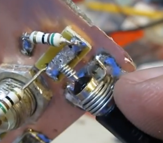
Using a "paper clip" ground to create the smallest possible measurement loop made a dramatic difference in the quality of my measurements! (as shown below)

"Paper clip" probe ground

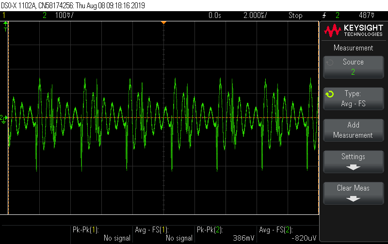
Here is an example of the ripple and voltage transients which originally motivated me to post this question. In this case the probe tip is applied to the 5V rail and the probe ground is connected to a grounded mounting hole several inches away using the probe's alligator grounding clip (pk-pk ripple is 386 mV):

Large apparent pk-pk ripple due to poor probing strategy

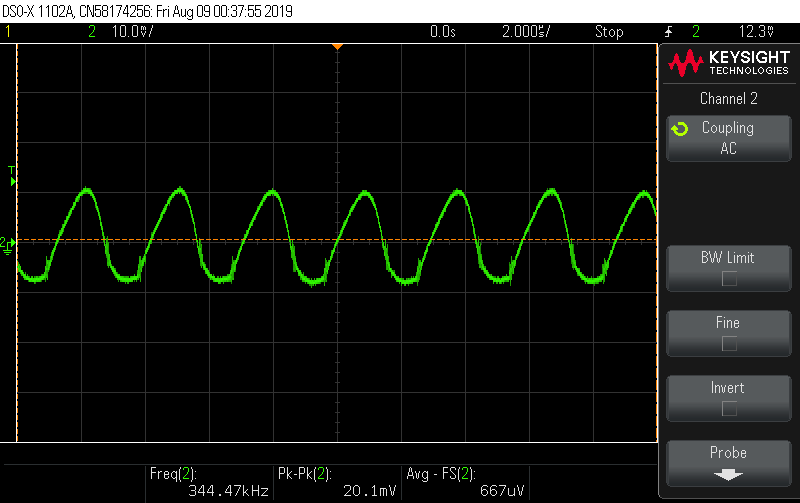
Now that same supply, with no other change and supplied power by a bench-top power supply, is probed using the "paper clip" ground point directly across the bypass capacitor nearest the output of the DC-DC SMPS 5V output (pk-pk ripple is 20.1 mV, well within the DC-DC module's specification):

Actual pk-pk ripple with proper probing technique

In the end, this new probing method even allowed me to pinpoint a previously un-diagnosed noise source in the form of an ornery charge-pump based TTL -> RS232 transceiver which could be squelched by adding a second 1 uF ceramic bypass capacitor near the source.

\$\endgroup\$

Your Answer

By clicking “Post Your Answer”, you agree to our terms of service and acknowledge you have read our privacy policy.

Not the answer you're looking for? Browse other questions tagged or ask your own question.