0
\$\begingroup\$

I am having issues with this previously designed circuit from a former co-worker. What we want it to do is turn on the LED when IN1 of TPS2121 (Power mux) is chosen as the output. According to the datasheet ST is pulled high when the output is Hi-Z or IN1 and pulled low when IN2 is powering the output. The LED is part of the switch PVA6LRE21141 I can't find the forward voltage it requires but with the current design, voltage across the diode is only 2.6V.

I do not understand his BJT circuit, the LED is not very bright at the status pin I only see 3.1V. I am trying to get it to turn brighter. Can someone explain the purpose of R14 and the way it is connected. Only R13 seems to affect the brightness, except I cannot decrease it any lower than 6K or I would violate the specifications of the TPS2121 ST pin. The ST pin requires a pull up from 6K-20K.

I think he used a BJT with C8 and R15 to create a ramp up effect for the LED. I do not think the ramp up is that necessary. Is there anyway I can change this design without having to change the PCB or as little as possible so that the LED can turn on brighter? I am considering changing Q1 to a mosfet with common footprint and removing C8. Thanks in advance for your help!

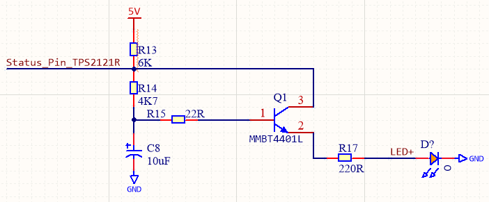
BJT design

\$\endgroup\$
1
  • \$\begingroup\$ can you give a photo of the pcb, maybe some parts can be fitted differently to good effect, \$\endgroup\$ Commented Jul 31, 2019 at 11:23

1 Answer 1

2
\$\begingroup\$

All of the current to the LED has to flow through R13 -- this is going to be your biggest limiting factor, particularly because R13 is already at the minimum resistance called out in the TPS2121 datasheet.

I wonder if your former coworker used a circuit designed for a push-pull output, where the TPS2121 has an open drain?

Changing to a MOSFET will only make things worse -- the base-emitter voltage of Q1 will be around 0.6V normally (it's only 0.5V here, probably because of the low current). A FET would need more than that from gate-source to turn on.

It would be a board mod, but connecting the collector of Q1 to +5V should result in immediate and delightful results. If you pulled C8 off of the board, you could replace R14 and R15 with zero-ohm resistors (R13 would provide any necessary current limiting to the base of Q1).

\$\endgroup\$
2
  • \$\begingroup\$ Hi Tim, thank you for response. Yes connecting the collector directly to 5V should solve my problem. I was trying to see if there is a way without modding. I think at the end of the day this is still the only way to be within spec of the TPS2121. The modification isn't that bad but it'd be more difficult to do it for 100+ boards.Thanks for your help \$\endgroup\$
    – k051819
    Commented Jul 31, 2019 at 18:46
  • \$\begingroup\$ there might be a way without modding, what is the layout? \$\endgroup\$ Commented Aug 1, 2019 at 5:04

Your Answer

By clicking “Post Your Answer”, you agree to our terms of service and acknowledge you have read our privacy policy.

Not the answer you're looking for? Browse other questions tagged or ask your own question.