I'm studying the inverter with active load, whose scheme is the following:
Now, the author of my book says:
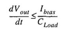
"We have to ensure a proper large-signal driving of the output node. The load of the inverter is always a capacitance (otherwise, a finite resistance would dissolve the voltage gain) but during transients, the circuit must provide a drain or sink current to charge or discharge that capacitive load. When the current is provided by the input transistor we have no limitations. In contrast, when the current is furnished by the active load, we have an upper limit. It is given by the current generated by the active load itself. This, in turn, sets the slew rate limit
where Cload is the total output capacitance"
I would appreciate if someone can give me some hints on how to calculate the slew rate. Suppose I give a large swing at the input voltage, then what kind of reasoning should I do in order to calculate the slew rate for this circuit? Why do we have that "When the current is provided by the input transistor we have no limitations. In contrast, when the current is furnished by the active load, we have an upper limit"?
Thank you


