About your code:
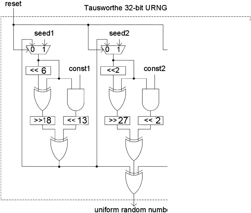
First, I think there is a mistake in your code, you miscoded the first branch by inverting the 18 shift and the 13 shift. (@Oldfart think the same)
Second, you have forgot the feedback in your code ! at the end of the process, s0 and s1 should receive the value stored inside snext0.
Third, you misunderstood how signal work (see below)
About tips and tricks for VHDL,
- You use the right libraries, others are either not standards or reserved for special use,
end Tausworthe; can be replace by end entity; without the name of the entity, I believe it is more clear that way.end Behavioural; can be replaced by end architecture; without the name of the architecture, I believe it is more clear that way.- you should try to avoid any hard coded values in your code ! This way, your code should more portable
- when you want to initialized a signal or a variable, instead of
x”0000000” you can use (others => ‘0’). I believe it is better because if you change the length of your vector it will still work.
I use a certain number of conventions (you may use others):
- The port of my entity are always starting by i_ for an input and o_ for an output and the remaing letters are in lower case,
- My constant are starting by
c_ and the remaining letters are in capital,
- My generics are starting by
g_ and the remaining letters are in capital,
- My signals are starting by
s_ and the remaing letters are in lower case,
- My variables are starting by
v_ and the remaing letters are in lower case,
- My types are starting by
t_ and the remaing letters are in lower case.
I have not changed all your code with my conventions.
The mistakes in your code:
- The way you coded your reset is not correct, you should test for an rising edge and then test for your synchronous reset
- Every signals you assign in your process should be in your reset (here o_data) and also some variables like
s0 and s1 which represent the output of a multiplexer and must take a special value at reset. As @TonyM said below,
In sensitive processes, variables are for use only to reference nodes within combinatorial logic trees.
- You make a very big mistake by confusing variables and signals!! google it !! Is a fundamental concept in VHDL! The more important to know is that: in a process, signals will be assigned there value at the end of the process, whereas variable will instantly take the value assigned. By only using signals, your code will not do what you want.
Here is your code corrected/changed:
library IEEE;
use IEEE.STD_LOGIC_1164.ALL;
use IEEE.NUMERIC_STD.ALL;


entity Tausworthe is

    Port(
        i_clock  :  in std_logic;
        i_reset  :  in std_logic;
        o_data   : out std_logic_vector(31 downto 0)
        );
end entity;


architecture Behavioural of Tausworthe is

    constant c_LENGTH : integer := 32;
    constant c_CONST1 : std_logic_vector(c_LENGTH-1 downto 0) := x"FFFFFFFE";
    constant c_CONST2 : std_logic_vector(c_LENGTH-1 downto 0) := x"FFFFFFF8";
    constant c_SEED1 : std_logic_vector(c_LENGTH-1 downto 0) := x"00002710";
    constant c_SEED2 : std_logic_vector(c_LENGTH-1 downto 0) := x"00002710";

begin
    process(i_clock, i_reset)

    variable s0,s1: std_logic_vector(c_LENGTH-1 downto 0); -- stages
    --variable output: std_logic_vector(c_LENGTH-1 downto 0); --NOT NEEDED, RIGTH ?
    variable s0int1,s0int11,s0int12,s0int21,s0int22,s0int23: std_logic_vector(c_LENGTH-1 downto 0); -- intermediate signals for s0
    variable b0,b1: std_logic_vector(c_LENGTH-1 downto 0); -- Intermediate b signals for each branch
    variable snext0,snext1,snext2,snext3: std_logic_vector(c_LENGTH-1 downto 0);
    variable s1int1,s1int11,s1int12,s1int21,s1int22,s1int23: std_logic_vector(c_LENGTH-1 downto 0); -- intermediate signals for s1

    begin

        if rising_edge(i_clock) then

            --if a reset occurs
            if i_reset = '1' then
                s0 := c_SEED1;
                s1 := c_SEED2;

                o_data <= (others => '0');


            --if no reset occurs
            else
            -- Here I'm coding the logic for the generator which includes the
            -- Shifts, XORs and ANDs. Intermediate signals are named according to branch
            -- s0,s1 then int (for intermediate) and 11,12,13,14 etc

            -- For first branch
            s0int1   :=  (s0(25 downto 0) & "000000" ); -- Shift left by 6
            s0int12  :=  (s0int1 XOR s0);
            b0       :=  ("000000000000000000" & s0int12(31 downto 18)); --Shift right by 18 NOT 13
            --b0 <= ("0000000000000" & s0int12(31 downto 13)); --Shift right by 13, OLD LINE
            s0int21  :=  (s0 AND c_CONST1);
            s0int22  :=  (s0int21(18 downto 0) & "0000000000000"); --shift left by 13 NOT 18
            --s0int22 <= (s0int21(13 downto 0) & "000000000000000000"); --shift left by 18, OLD LINE
            snext0  :=  (s0int22 XOR b0);


            -- For second branch
            s1int1   :=  (s1(29 downto 0) & "00"); -- Shift left by 2
            s1int12  :=  (s1int1 XOR s1);
            b1       :=  ("000000000000000000000000000" & s1int12(31 downto 27)); --Shift right by 27
            s1int21  :=  (s1 AND c_CONST2);
            s1int22  :=  (s1int21(29 downto 0) & "00"); --shift left by 2
            snext1   :=  (s1int22 XOR b1);

            --your shematic has a feedback !!!
            s0 := snext0;
            s1 := snext0; --Yes it is also snext0 and not snext1 according to your schematic

            --return the result
            o_data <= (snext0 XOR snext1);

            end if;

        end if;

    end process;

end architecture;
If I may give other advice:
I do not think you should initialize your variables or signals, even for me it is not clear but I believe that initialization is mostly used for simulation purpose and it is not (always) synthesizable. Try to avoid it, your initialization takes place during the reset for every signals and for variables which need it (see the remark of @TonyM below).
I can see that the 2 branch are identical, the only difference are the constant used and the value of the shift, furthermore, it seems that the picture was cropped and that more branch may exist, so you should consider using a function that take in parameters the constant to use and the values of the shift, it will make your code better I believe, google vhdl function
pure function Tausworthe_branch(const : std_logic_vector; shift1 : integer, shift2 : integer; shift3 : integer) return std_logic_vector;
the remarks made by @TonyM is relevant, if you want your logic to be synchronous use the above code, but if you want pure combinatorial logic, you should use concurrent statement. It depends on what you want to achieve, to my it seems that the output and the feedback should be synchronous, otherwise the system would be instable (thanks to @Simon for pointing that).
I have left the things like "000000" (6bits at 0) but I think that it should removed !! and replace by this: (5 downto 0 => '0'). Consquently, you should replace shift lines like this one :
s0int1 := (s0(25 downto 0) & "000000" ); -- Shift left by 6
by:
s0int1 := (s0(25 downto 0) & (5 downto 0 => '0') ); -- Shift left by 6
or even more portable but less readable:
constant c_LENGTH : integer := 32;
constant c_SHIFT_LEFT : integer := 6;
s0int1   :=  (s0(c_LENGTH-c_SHIFT_LEFT-1 downto 0) & (c_SHIFT_LEFT-1 downto 0 => '0') ); -- Shift left by 6
This last form is what I would use inside a function.
Last advice: do a complete tutorial, you know too little about VHDL.
About your Simulation problem:
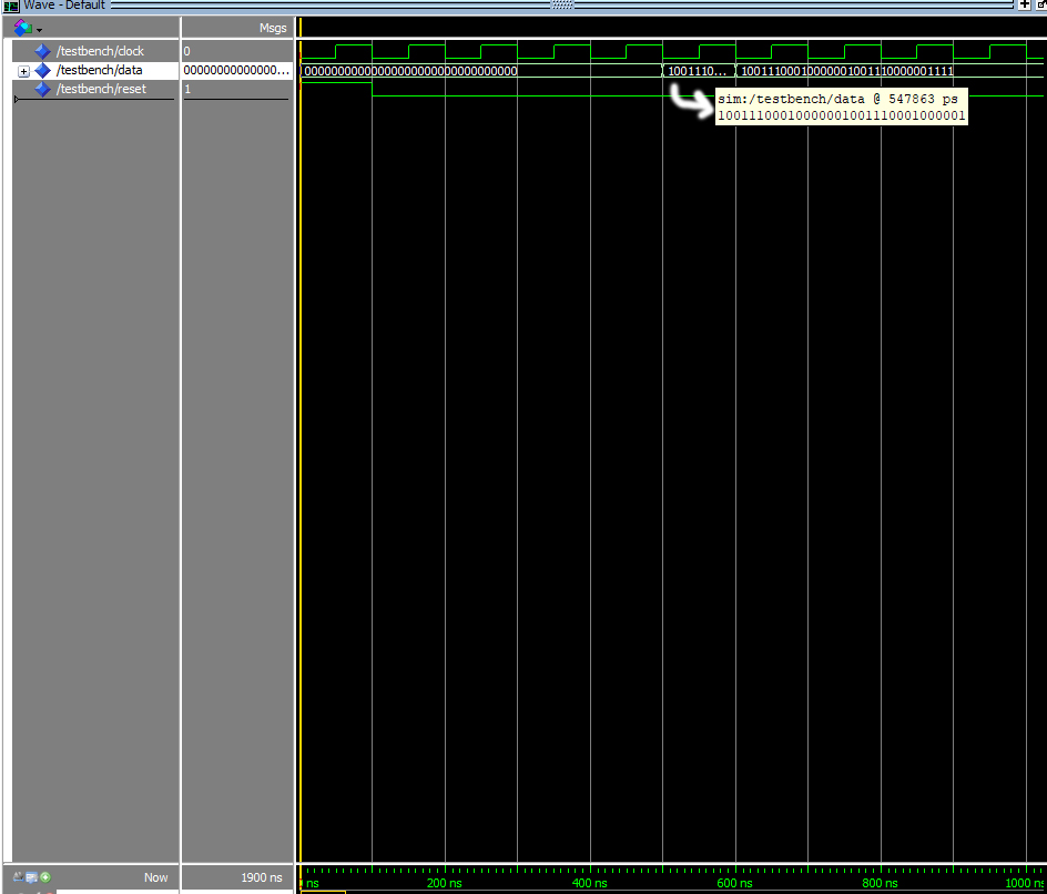
I have not simulated the code, but your problem probably comes from the fact that you used signals instead of variables at some place.
Long post :-)


