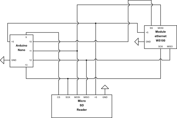
I would like to create a small web server to enable or disable devices via ethernet connection, except that the network module and the SD reader did not seem to work if connected simultaneously. That is, if I remove the SD reader the Ethernet module starts to work perfectly.
Below I leave the current version of code used for the tests:
#include <SPI.h>
#include <Ethernet.h>
//#include <SD.h>
#include "SdFat.h"

SdFat SD;

#define SS_ETH 10
#define CS_microSD 9

byte mac[] = {
  0xDE, 0xAD, 0xBE, 0xEF, 0xFE, 0xED
};

IPAddress ip(192, 168, 1, 177);

EthernetServer server(80);

void setup() {
  Serial.begin(9600);

  pinMode(SS_ETH, OUTPUT);
  digitalWrite(SS_ETH, HIGH);

  Serial.println("Initializing SD card...");

  if (!SD.begin(CS_microSD)) {
    Serial.println("initialization failed!");
  } else {
    Serial.println("initialization done.");
  }

  // start the server
  server.begin();
  Serial.print("server is at ");
  Serial.println(Ethernet.localIP());
}


void loop() {
  // LOOP
}
output produced by the program via serial:
Initializing SD card...
initialization done.
server is at 255.255.255.255
If instead I remove the microSD from the reader and restart the circuit I get:
Initializing SD card...
initialization done.
server is at 0.0.0.0
Hardware:
- Arduino Nano
- W5100 ethernet module ( https://www.ebay.it/itm/SHIELD-MINI-W5100-modulo-ETHERNET-per-ARDUINO-ART-CV05/262454631406?hash=item3d1b83dbee:g:ltYAAOSwHsRYE0KC )
- microSD reader ( https://www.ebay.it/itm/Lettore-micro-SD-card-reader-writer-pic-arduino-raspberry-shield-ART-CL06/261625448910?hash=item3cea1789ce:g:tF0AAOSwAYtWOclu )
Wiring diagram
- pin 9 -> CS microSD
- pin 10 -> SS Ethernet
- pin 11 -> MOSI
- pin 12 -> MISO
- pin 13 -> SCK

simulate this circuit – Schematic created using CircuitLab
Update 1: Thanks to the suggestions of @Juraj I tried to disconnect the MISO pin of the SD reader and the IP assignment was successful. Furthermore the SD.h library has been replaced with SdFat.h ..
The card reader has an LVC125A level converter as shown in this image: https://e-radionica.com/media/catalog/product/cache/1/image/9df78eab33525d08d6e5fb8d27136e95/d/s/dsc_1819.jpg
Also here is the LVC125A level converter datasheet: https://www.alldatasheet.com/datasheet-pdf/pdf/171748/TI/LVC125A.html
UPDATE 2: a hardware modification to the reader is required to solve the problem since the MISO pin remains permanently enabled. https://forum.arduino.cc/index.php?topic=360718.msg2942160#msg2942160
