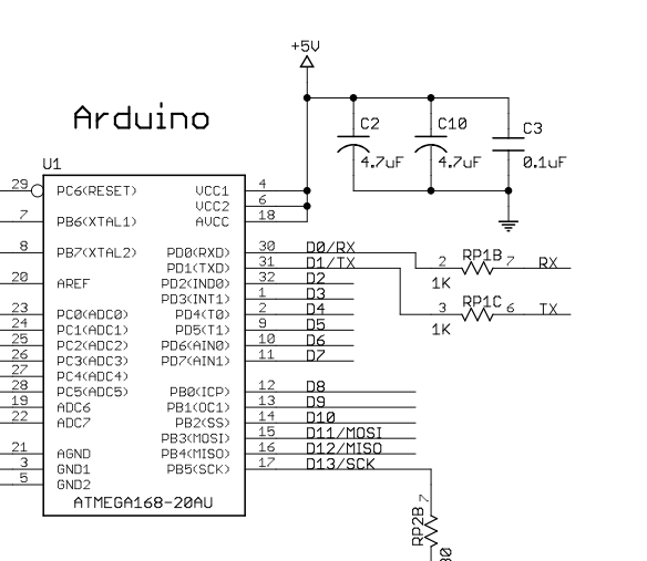
(Thanks for all people commented, having my answer improved greatly).
These are called bypass capacitors (see fragment from What-is-a-bypass-capacitor):
A bypass capacitor is a capacitor that shorts AC signals to ground, so
that any AC noise that may be present on a DC signal is removed,
producing a much cleaner and pure DC signal.
A bypass capacitor essentially bypasses AC noise that may be on a DC
signal, filtering out the AC, so that a clean, pure DC signal goes
through without any AC ripple.
For example, you may want a pure DC signal from a power source.
Remark from tangrs below:
The AC noise is created by spikes of power consumption every time the
micro-controller switches its internal transistors (i.e. on every
clock pulse).
Regarding switching time, remark of Peter Smith:
Depending on the internal switching speed (probably not an issue
here), low ESL devices (as found in reverse geometry devices) are
sometimes recommended
The values matter, not the exact values, but in the case above to have values which are distinct (or at least in certain ranges), see also the remark of Hearth below:
The point is more to have capacitors with low ESR as well as ones with high capacitance, not just to have distinct capacitance values. Or just put a few identical ones in parallel to lower the ESR and increase the capacitance.
Regarding values (remark from NGuyen):
Note there is an antiresonance effect when using different values in
parallel which can make things worse if the antiresonance spikes fall
on frequencies your circuit operates at. . It is not recommended to
mix multiple values when things really matter. Use multiple of the
same value in parallel to get lower inductance and higher capacitance
while avoiding antires spikes.
See link: Antiresonance....
In this question (/where-did-the-value-of-0-1uf-for-bypass-capacitors-come-from), it is explained why the 0.1uF is used.
If you omit these, the voltage levels are less clean, which can result in strange behavior of the IC connected.

