0
\$\begingroup\$

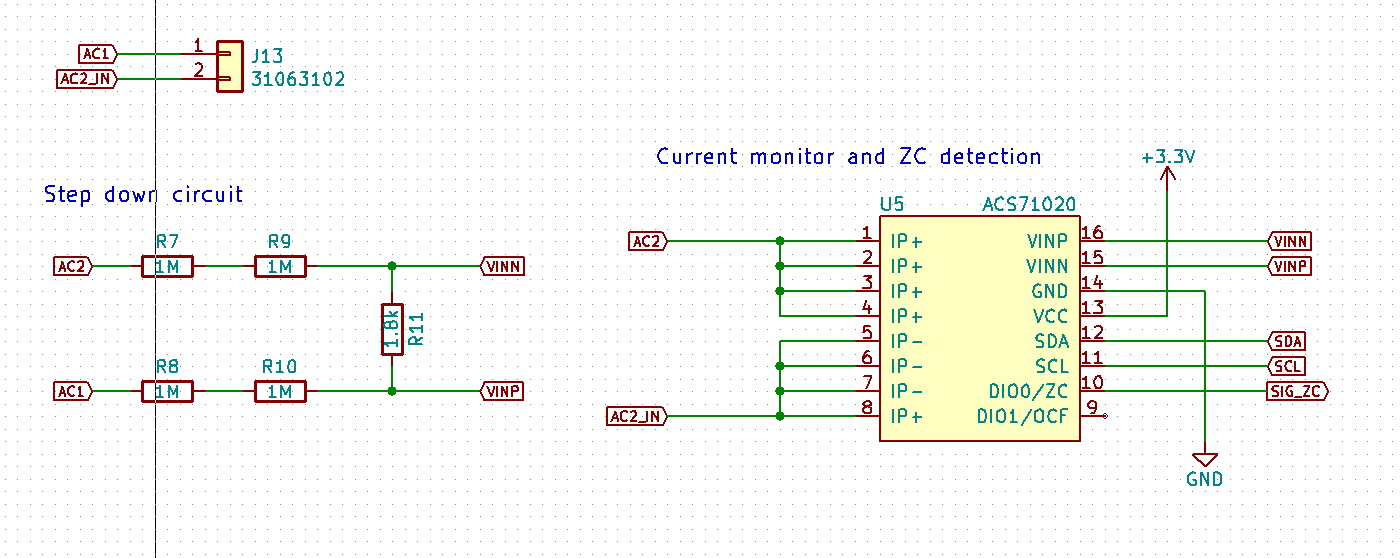
I've added an Allegro ACS71020 to my Arduino project to measure power usage (circuit shown below).

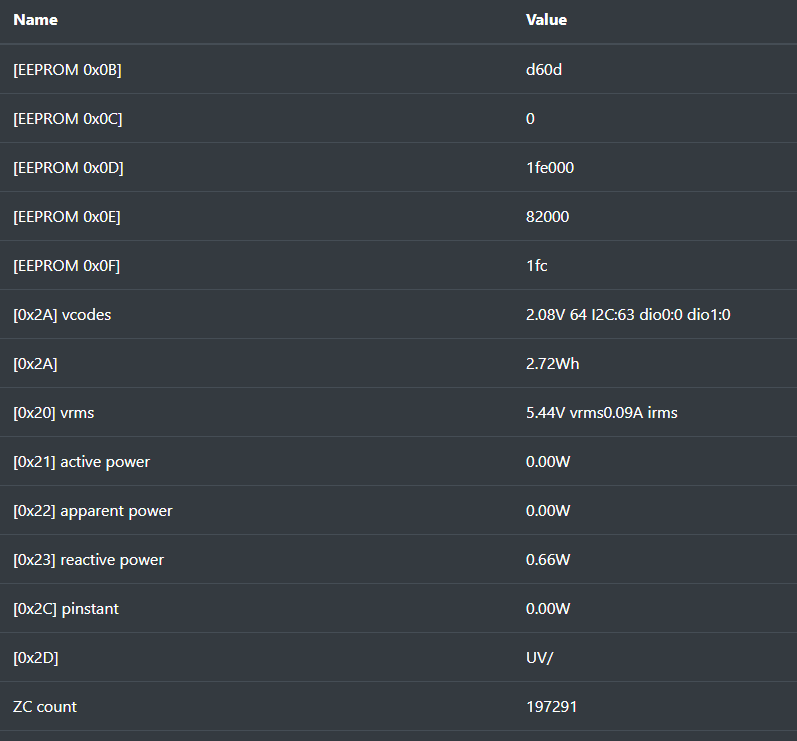
I can connect to I2C on 0x63 and I get response (check the image below) - but the values do not change if I have AC connected or not, nor if I connect some load.

And ZC is working even if mains is not connected.

What am I doing incorrectly? Is there some initialization that I need to do before I start using it?

I used reference design with R_sense=1.8k (for 240VAC).

Thank you in advance.

part of schematic diagram

I2C register values

\$\endgroup\$
4
  • \$\begingroup\$ Where are the pullup resistors for SCL and SDA? Are you sure that the software is actually updating the output if it can't connect with the sensor? \$\endgroup\$ Commented Aug 16, 2019 at 19:09
  • \$\begingroup\$ It isn't clear on your schematic where the line and load is connected. \$\endgroup\$
    – Mattman944
    Commented Aug 16, 2019 at 22:33
  • \$\begingroup\$ This is just an excert from the bigger schematics. For i2c pullups I use 4.7k resistors. Howevwr the communication is working fine. It is functionality that I cant setup. \$\endgroup\$
    – david
    Commented Aug 17, 2019 at 7:10
  • \$\begingroup\$ I also noticed that in cca 5 sec intervals several values do change a bit but all the same if mains or additional load is connected or not. \$\endgroup\$
    – david
    Commented Aug 17, 2019 at 7:12

2 Answers 2

1
\$\begingroup\$

I think the ACS37800 might be the other solution (at least it looks like it will be fore me). I was getting the same results on the 71020 as others in this thread: stable communication (able to read and write), weird ZC with no input, but I noticed different results depending on if my power source was floating or not compared to the inputs. Going to the website I notice under the datasheet link:

"Not recommended for new developments. Refer to the ACS37800 which is pin to pin compatible." (probably should have read that before I started designing)

Looking at the 37800 datasheet the Vnn is fixed to device GND and ZC flag is by default on the voltage channel. My guess is that the 71020 was floating, but the 37800 now has Vnn to GND fixed which hopefully will have the ZC work as expected. It also looks like the 37800 works with both DC and AC while the 71020 (from what I read here) doesn't.

Side note: The 37800 datasheet also has a lot more information on how this device functions, what some of the features look like and some considerations when designing the device into your application.

I'm going to give this device a try, figured I'd shout out a possible solution here.

\$\endgroup\$
0
\$\begingroup\$

I too have recently included using this chip in a project but have yet to get it to work consistently.

I find the data read back from this chip to bounce around (unreasonably) by times or to vary significantly from what I get from a DMM. Even though I am using an isolated power supply to power the chip/microprocessor I am wondering if there is some isolated ground/ground loop problems. Don't know.

If I understand the data sheet correctly the vrms, irms and active power values (registers 0x20, 0x21) are the values calculated during the last half cycle. Try looking at the averaged values. If you set register 0x0C to some reasonable value (mine is currently set to 0x820 giving avg1=32 and avg2=16) try looking at the vrms and power average values (register 0x26/0x28 for short term average, avg1, and 0x27/0x29 for avg2). Note you will need to set the chip into "Customer Mode" first to write to register 0C ... and power cycle it after changing the value.

ZC count working even when no power connected? Seems very strange. I'll have to check what happens on my board. Haven't looked at that.

\$\endgroup\$
5
  • \$\begingroup\$ I too find the ZC (DIO_0 pin) behaves strangely. With a 16VAC transformer source (connected to a Canadian 115V/60Hz mains) I get nice clean 16.6 ms pulses, 32us wide. If I remove the voltage source from the test bed (ie. no power, voltage or current under test) I still get pulses from DIO_0. There is an underlying 16.6 ms stream of pulses, but there are now spurious ZC events generated whenever I read from registers. All these events are nice clean 32us pulses so they are being generated by the chip circuitry. 12VDC source (switching PS) connected shows regular pulses at 80-100ms intervals. \$\endgroup\$
    – DougC
    Commented Aug 31, 2019 at 8:16
  • \$\begingroup\$ Hi Doug. Thank you for your response. I tried what you suggested: On [0x26] and [0x28] I'm getting raw value of ~112 when no AC is connected and ~575 when I connect AC - no changes if I connect load or not. [0x28] is changing slowly between that values what is to be expected. [0x27] and [0x29] is mostly 0 (I did notice few high spikes - very rare). There is no detailed documentation for registers [0x26,0x27,0x28,0x29] other than number of bits. Weird is also that [0x2A] vcodes is changing between 0 and 1 if I connect AC or not. \$\endgroup\$
    – david
    Commented Sep 1, 2019 at 10:39
  • \$\begingroup\$ The latest version of the datasheet shows an alternate connection method using capacitive coupling. This initially seemed to work better for me ... with stable readings at low AC current levels. However, as the load draws more power, the results became more and more inconsistent with reality. I am clearly missing something in the proper use of this chip. \$\endgroup\$
    – DougC
    Commented Sep 18, 2019 at 16:44
  • \$\begingroup\$ The new datasheet also silently removes all mention of measuring DC power levels (no acknowledgement of this fact in the Revision History section), a feature I was hoping to use. I have now spent too much time trying to get this chip to work and so will choose another option. Too bad as it appears to be a really useful chip if I could get it to work reliably. \$\endgroup\$
    – DougC
    Commented Sep 18, 2019 at 16:46
  • \$\begingroup\$ I too need to choose another solution :( Please make a post if you find any suitable replacement. \$\endgroup\$
    – david
    Commented Sep 21, 2019 at 9:10

Your Answer

By clicking “Post Your Answer”, you agree to our terms of service and acknowledge you have read our privacy policy.

Not the answer you're looking for? Browse other questions tagged or ask your own question.