1
\$\begingroup\$

I'm quite new to electronics and I'm afraid I'm missing some basic knowledge. (also please forgive me if I'm not always using the right terminology)

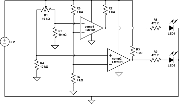
I'm trying to use a potentiometer (R1 in the schema below) to divide input voltage and divide it between the two other terminals. The idea is that when the wire to comp1 has almost no resistance, the LED1 will light up. When moved to the other end, LED1 should be unlit when the voltage drops to a theoretical 4V (that's what the voltage divider connected to both V- terminals of the comparator is for). When the voltage for comp2 is higher than 4V, LED2 should be lit.

When I create this on my breadboard, none of the LEDs will light up, no matter how I position the wiper of the potmeter.

What am I doing wrong? Is it wrong to use the 5V for both the Vcc of the comparator and the "logic voltage" for its pullup resistor?
schematic

simulate this circuit – Schematic created using CircuitLab

EDIT

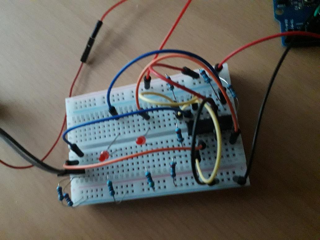
I implemented this circuit as follows:

enter image description here

The yellow wires are connected to the inverting inputs of the comparator, the blue and orange wires are meant to distinguish the circuits for both LEDs. The grey and black wires are connected to the potmeter.

(btw I see I've placed the resistors "after" the LEDs, but I don't think that would make any difference in this case?)

\$\endgroup\$
3
  • 1
    \$\begingroup\$ I just checked: the LM2901 has an open collector output. Your LED's will work better if you move them, with the resistor, in place of R2,R3. For the rest the circuit looks OK (I did not check the full datasheet though). I would say it is time to check your connections. Or did you buy the parts from some dodgy website? \$\endgroup\$
    – Oldfart
    Commented Aug 18, 2019 at 9:22
  • \$\begingroup\$ Oldfart means that the LEDs won't work any better but the circuit will be a little more efficient if it's not sinking current when the LEDs are off. \$\endgroup\$
    – Transistor
    Commented Aug 18, 2019 at 12:09
  • \$\begingroup\$ Long shot: are your comparators decoupled? \$\endgroup\$
    – winny
    Commented Aug 18, 2019 at 19:53

2 Answers 2

1
\$\begingroup\$

Looking at the Electrical Characteristics of the LM2901, I see that the common-mode input voltage range is 0 to Vcc-1.5 volts. You have the negative inputs at 4 volts, or Vcc-1, which is outside the recommended operating range. The comparators are not guaranteed to work correctly when the common mode voltage is within 1 volt of the positive supply.

Try changing R6 to 2K, and R7 to 3K, to bring the common-mode voltage within the legal range.

\$\endgroup\$
2
  • \$\begingroup\$ OK, I'll give that a try \$\endgroup\$
    – gatukok
    Commented Aug 19, 2019 at 17:52
  • \$\begingroup\$ Although Transistor's answer gave me confirmation about the correctness of the circuit (and some additional explanation about open collector comparators, thank you for that), this answer helped me solve the problem (in fact it came down to rtfm I guess). I needed the 1:4 ratio used in my voltage divider, so I used my Arduino's 3.3V pin as supply for both potmeter and voltage divider and it works like a charm. Thank you for your help :) \$\endgroup\$
    – gatukok
    Commented Aug 20, 2019 at 7:05
0
\$\begingroup\$
  • For a nominal 5 V supply R6 and R7 provide a nominal 4 V volt input to the inverting inputs. This voltage will vary with the supply voltage.
  • R1 provides an unusual means of adjusting the threshold voltages.
    • With R1 fully left (0%) COMP1+ will be at half supply (2.5 V nominal) and COMP2+ will be at supply (5 V nominal). In this condition COMP2 should turn on and LED2 should light.
    • With R1 fully right (100%) the situation is reversed and COMP1 should turn on and LED1 should light.
  • The comparators have open collector outputs but you have your pull-up resistors as required so all looks OK there. You could eliminate R8 and R9 but they're not doing any harm.
  • Some decoupling capacitors should be added to the power pins of the comparators.

As drawn you should be able to get the LEDs to light. As a practical circuit you may have a bit of a problem as the reference voltages will vary with the supply voltage. R1's wiper should really be fed from a stabilised voltage so that the comparators' reference voltage remains constant regardless of the supply voltage which is expected to fall.

Post a photo of your (tidy) breadboard implementation and we'll see if we can spot an error.


Just out of curiosity, why can R8 and R9 be eliminated? I thought the LEDs would draw too much current without a resistor?

schematic

simulate this circuit – Schematic created using CircuitLab

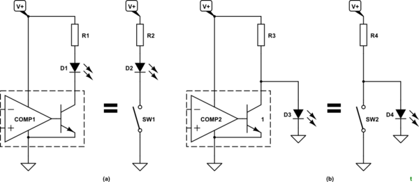
Figure 1. (a) A typical comparator LED driver using the open-collector output and the equivalent switch circuit. (b) Your circuit with R8 and R9 eliminated and the equivalent circuit.

Figure 1a should be clear enough. The LEDs would come on in the opposite way to your design but this could be solved by swapping the inputs.

Figure 1b should be clear enough with the equivalent circuit using SW2. When SW2 is open the D4 LED current is limited by R4 so there is no need for the additional resistor above D4. When SW2 closes D4 is shorted out and so it goes off. The downside, as mentioned earlier, is that R4 is now passing more current than it was while the LED was lit (because the full supply voltage is across it now).

Or does the comparator limit the current somehow?

No. Hopefully this is clear now.

\$\endgroup\$
9
  • \$\begingroup\$ I believe that being the whole circuit ratiometric we shouldn't be in the need of stabilized reference and pot supply. \$\endgroup\$
    – carloc
    Commented Aug 18, 2019 at 12:20
  • \$\begingroup\$ Consider, for example, the case where R1 and R4 are 2.5k and 10k. COMP2 will see the same voltage on the two inputs regardless of the supply voltage. \$\endgroup\$
    – Transistor
    Commented Aug 18, 2019 at 12:24
  • \$\begingroup\$ Sorry, I can't follow you. You say "something" happens regardless the supply voltage, which is exactly my point. So I don't need stabilized supply. \$\endgroup\$
    – carloc
    Commented Aug 18, 2019 at 12:40
  • \$\begingroup\$ No problem. With a 5 V supply R6 and R7 provide 4 V to the inverting inputs. With R1 and R4 at 2.5k and 10k the non-inverting inputs will also see 4V. As the supply voltage goes up and down the two ratios remain constant, the two voltages move proportionately to the power supply and the circuit won't switch. The principle applies for any setting of R1. Both the threshold and the voltage being monitored will change in unison. \$\endgroup\$
    – Transistor
    Commented Aug 18, 2019 at 12:49
  • \$\begingroup\$ AHH I see now. I thought the OP was after a "wiper position switch" a kind of position control. But if he's for voltage threshold instead you are of course plain right. I reread the question but still not clear to me which is the system input. \$\endgroup\$
    – carloc
    Commented Aug 18, 2019 at 12:57

Your Answer

By clicking “Post Your Answer”, you agree to our terms of service and acknowledge you have read our privacy policy.

Not the answer you're looking for? Browse other questions tagged or ask your own question.