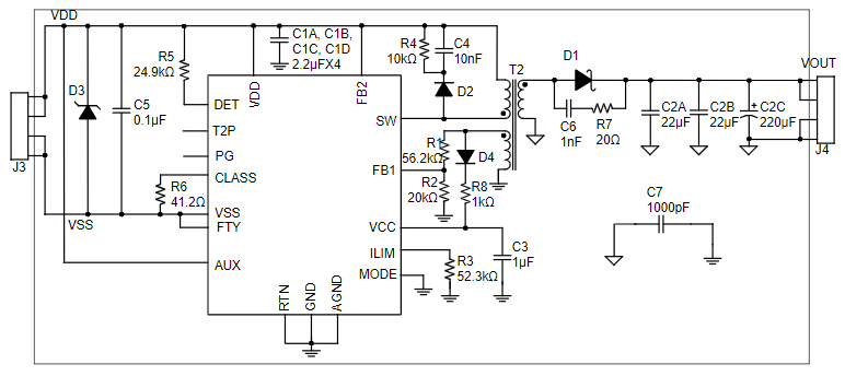
I am working on a PoE design for the first time that supports 100 Mbps. I plan on using the mEZS84801A evaluation board that uses MP8007 as a reference design to do all the signature detection, classification and DC/DC converter as shown below. I need an output of 12 V to supply the camera which will be the PD. It will draw around 8 W during continuous run time.
I need some advice for the circuit design before the MP8007, involving the RJ45 and transformer. The main concern is, we do not what the customer will be using for their PSE, is there a way to design for both Mode A and B so that when they plug the cable in with their PSE, the design can accommodate for an Endspan switch or if they decide to use a Midspan and Ethernet switch?
The IC is compatible for both modes but I noticed that the magnetic transformer after the RJ45 is different depending on mode. Mode A, the pairs 4,5 and 7 and 8 are left unconnected since power is from the data pairs, whereas Mode B the spare pairs are connected. I am thinking if both cannot be supported at once, I would have population options to select between modes. But ideally if there is a way to make a design that can support both modes without needing to modify the PCB it would be much better.

