0
\$\begingroup\$

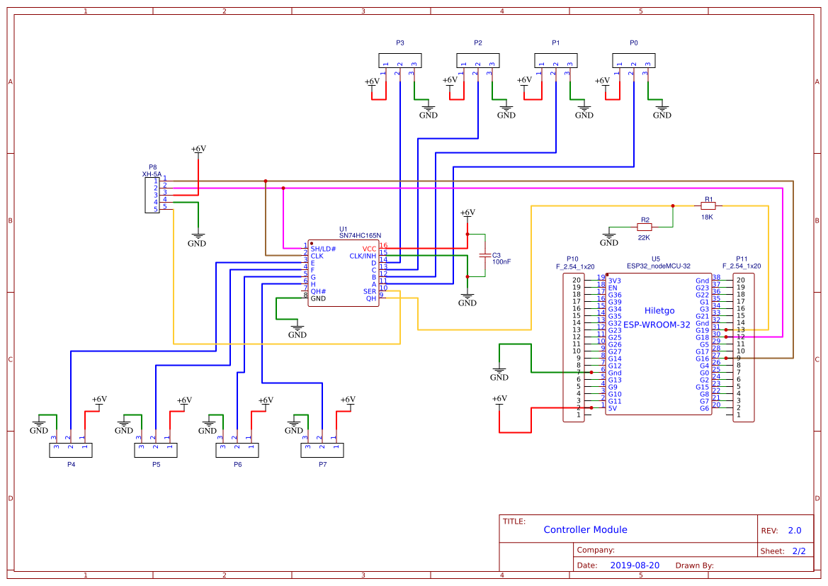
In this circuit I have sensors that are rated for a minimum of 6V connected to a 74HC165 which passes its output to the MISO pin of an ESP32. I was hoping a simple divider to convert the 6V from the shift register to 3.3V for the ESP32 would work ... but no.

The ESP32 is unable to process the input consistently, delivering erratic output results. Interestingly, it all works perfectly if I remove the resistors for the voltage divider and power it all with 5V. The sensors can apparently handle the lower voltage fine ... but they need to be operated at 6V minimum.

Should I use a linear regulator or switching regulator instead of a voltage divider? Or is there something else I'm missing?

Much thanks,

circuit schematic

\$\endgroup\$
4
  • \$\begingroup\$ That is not a voltage divider from the 165 to the ESP32. .Your R1 is at the wrong side of the R2. \$\endgroup\$
    – Oldfart
    Commented Aug 26, 2019 at 16:32
  • \$\begingroup\$ Please provide links to the manufacturer's datasheets (not vendor web pages) for the ESP module, the HC165, and the sensors. \$\endgroup\$ Commented Aug 26, 2019 at 17:10
  • \$\begingroup\$ Either like Voltage Spike showed in his answer, or get a dedicated level shifter IC (can't look them up right now, but search DigiKey or Mouser for Level Shifter and you will find a ton). \$\endgroup\$
    – Snellface
    Commented Aug 26, 2019 at 17:21
  • \$\begingroup\$ My bad. The drawing is wrong. The circuit is actually as Voltage Spike suggested. \$\endgroup\$
    – puckhead
    Commented Aug 26, 2019 at 19:33

3 Answers 3

0
\$\begingroup\$

Chances are high that in addition to feeding 6V into a pin that's not even 5V tolerant, you're trying to run a 74HC part with woefully inadequate pin voltages.

The easiest solution is the proper voltage divider, run your sensor at 5V, and use a 74HCT165 (note the 'T' in the part designation). The 74HCT line is made to run from 5V and accept TTL input voltages -- which are, happily, about the same as what comes out of CMOS being driven from 3.3V.

If you absolutely must run your sensor at 6V, then you'll need proper voltage translation between it (or them) and your 74HCT165.

For transitions that are slower than about 100Hz or so (and maybe up to the low kHz), this should work well -- and you can collect Q1, R1 and R2 into a pre-biased transistor, for more savings.

  • Choose R3 to be around 1k\$\Omega\$ to 10k\$\Omega\$
  • Choose R1 and R2 so that if they were an unloaded voltage divider, they'd have a voltage of around 1.4 - 2V when the sensor output is on (i.e., \$\frac{R1}{R1 + R2} \simeq \frac{1.4\mathrm{V}}{V_{out}}\$). That uses the transistor's Vbe to make a really soft threshold of around half the sensor output voltage.
  • Choose R1 and R2 so that their parallel equivalent is equal to about five times R3 or less (i.e., \$\frac{R1\,R2}{R1 + R2} \le 5 R3\$). That makes sure that the transistor is well into saturation when its on.
  • Don't sweat getting the numbers for R1 and R2 exact.
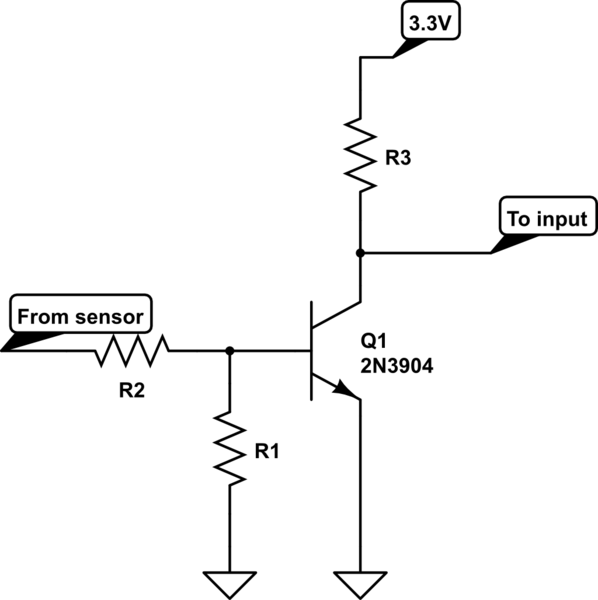
schematic

simulate this circuit – Schematic created using CircuitLab

\$\endgroup\$
6
  • \$\begingroup\$ Thanks. I'll look into the 74HCT. The datasheet for the 74HC165 listed a 6V max. The sensors are rated 6V - 36V. Some of the cheaper sensors actually work fine at 5V, but the better ones have a 6V min and some sort of onboard cutout below that as well. I thought about a divider at each sensor but figured the only problem point would be the one pin to the ESP32. \$\endgroup\$
    – puckhead
    Commented Aug 26, 2019 at 19:42
  • \$\begingroup\$ I don't like running chips right against their limits like that, and if 6V is the absolute lowest it may be better to just run the sensor at 12V or some other comfortable middle range, and use a voltage divider or pre-biased transistor inverters to do the voltage translation. \$\endgroup\$
    – TimWescott
    Commented Aug 26, 2019 at 20:11
  • \$\begingroup\$ Thanks very much Tim. So you would advise a voltage divider at each sensor? \$\endgroup\$
    – puckhead
    Commented Aug 27, 2019 at 19:45
  • \$\begingroup\$ I'd use a pre-biased transistor, like the onsemi.com/pub/Collateral/FJN3305R-D.pdf, with a resistor from collector to 3.3V. But a voltage divider would work. \$\endgroup\$
    – TimWescott
    Commented Aug 27, 2019 at 20:33
  • \$\begingroup\$ Check mark goes to you Tim. The design uses proximity sensors which are on-off with a max of 300 mA, but they shouldn't run anywhere near that. Would there still be benefits with a pre-biased transistor? \$\endgroup\$
    – puckhead
    Commented Aug 27, 2019 at 22:40
1
\$\begingroup\$

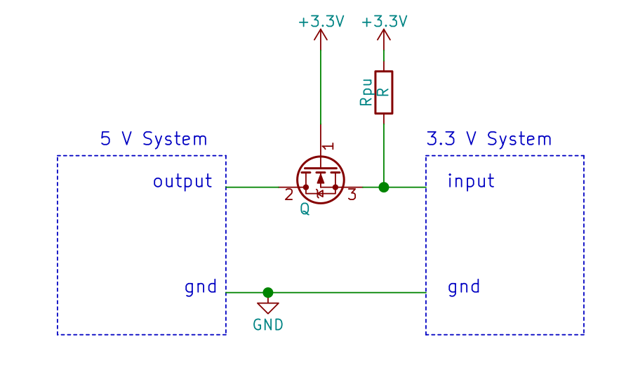
You have to use a logic level shifter IC. You can use a dedicated IC which can translate the signal from one level to the other. you can also use the below circuit if there is only one signal to convert from one voltage level to the other.
The MOSFET can be logic N type MOSFET. Image and many other solutions from this link: https://next-hack.com/index.php/2017/09/15/how-to-interface-a-5v-output-to-a-3-3v-input/

As other answers have mentioned, there is also a need to check once the overall design and supply voltage level options to make sure you are following the recommended specification from the respective datasheets. The particular sample may work, but not always. enter image description here

\$\endgroup\$
2
  • \$\begingroup\$ If the OP runs the HC165 at 6V (or, technically, even at 5V) then they need voltage translation on the commands from the 3.3V system, too. \$\endgroup\$
    – TimWescott
    Commented Aug 26, 2019 at 20:10
  • \$\begingroup\$ i would then propose a bi-directional voltage level translator \$\endgroup\$
    – User323693
    Commented Aug 26, 2019 at 20:39
1
\$\begingroup\$

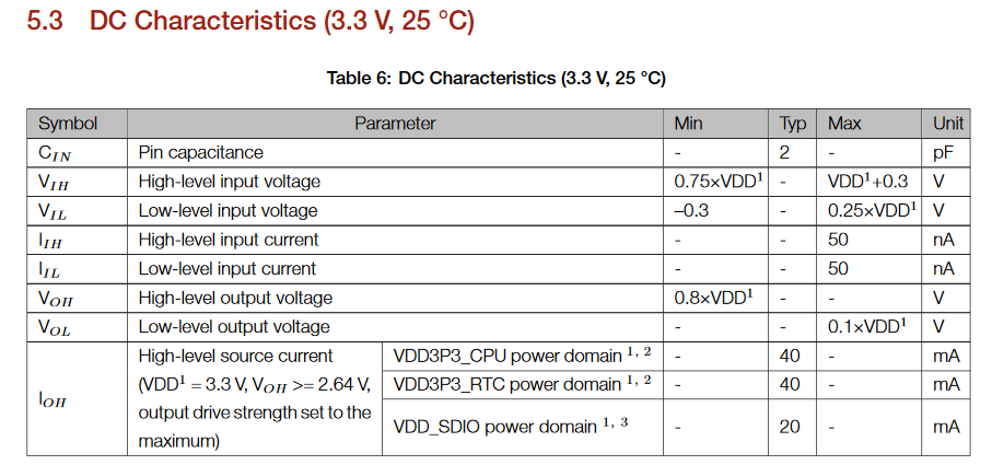
While the datasheet is not clear on what the absolute maximum ratings for the IO's are, I am certain that it's 3.6V. Usually "+0.3V" means that the inputs are protected with a diode that turns on at Vdd+0.3V. So this means don't tie Qh directly to the port of the ESP32, it could burn out the diode.

enter image description here

Source: https://www.espressif.com/sites/default/files/documentation/esp32-wroom-32_datasheet_en.pdf

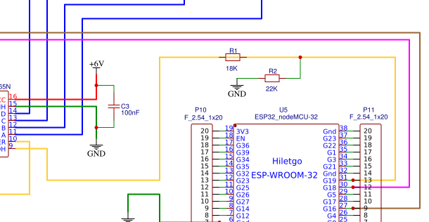
The resistor divider isn't working because it's not dividing the output voltage from Qh, it needs to look like this:

enter image description here

The Voltage output specs for the SN74HC165 are Voh = 5.99V and Vol = 0.1V, after the resistor divider this would be 2.7V for Voh and 0.045V for Vol, using a resistor divider is compatible range of the ESP32's Vih of 2.475V and Vil of 0.825

\$\endgroup\$
2
  • \$\begingroup\$ My bad. The drawing is wrong. The circuit is configured as you've shown. How did you edit that so cleanly? \$\endgroup\$
    – puckhead
    Commented Aug 26, 2019 at 19:33
  • \$\begingroup\$ BTW, I get 6V at Qh and 3.3V at pin 31 on the ESP32, leading me to believe it should work fine. \$\endgroup\$
    – puckhead
    Commented Aug 26, 2019 at 19:49

Your Answer

By clicking “Post Your Answer”, you agree to our terms of service and acknowledge you have read our privacy policy.

Not the answer you're looking for? Browse other questions tagged or ask your own question.