I have code that works using Arduino.
Because I wanted to size down the project, I replaced it with an Attiny841.
Process:
I soldered the 841 on an adapter and checked all pins using a multimeter for cold joints.
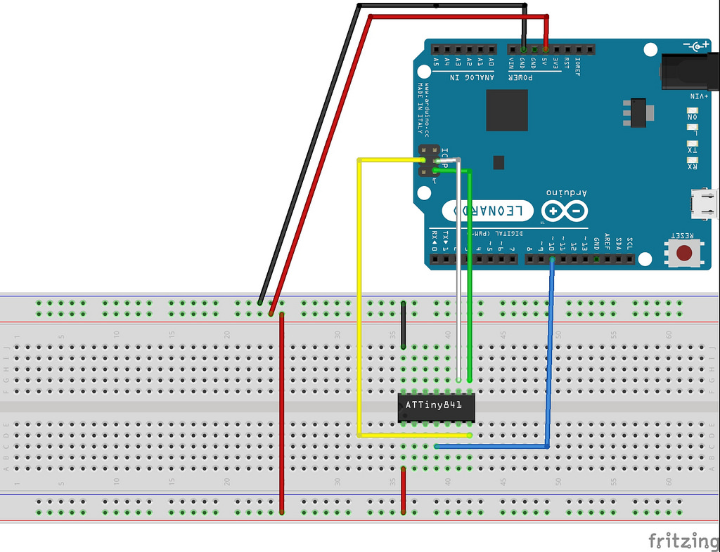
Then I connected the pins using this schematic from http://elecrab.com, but with a cap for RESET in addition:
I used the online Arduino environment to burn the ArduinoISP sketch to my Arduino.
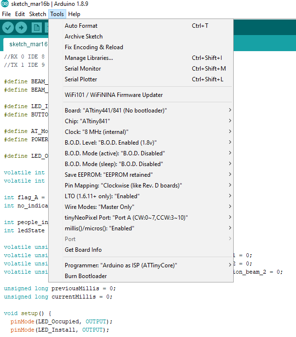
Then I used the offline Arduino program, using ATTinyCore as such:
I burned the bootloader and it did so succesfully.
I then copy-pasted my own sketch in the offline environment and uploaded it, which also worked without a single error.
(For some weird reason I cannot burn the ArduinoISP using the offline program, hence the two-step method.)
Sketch:
I left my sketch unaltered, except for the selected pins which became:
#define BEAM_One 2
#define BEAM_Two 3

#define LED_Install 4
#define BUTTON_Install 5

#define AT_Mode 6
#define POWER_On 7

#define LED_Occupied 10
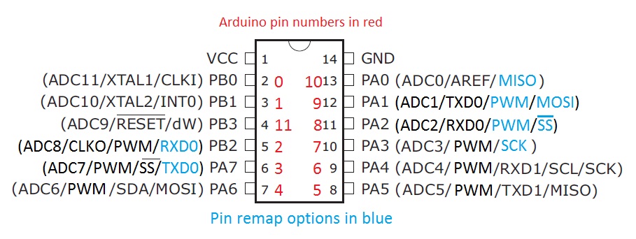
Basically, I thought, 841 physical pins 11 and 12 are TX/RX and 2 to 4 are special cases, so I can simply select pins 5 to 10 and 13 for I/O.
I then choose the above pins, using the pin mapping in the ATTinyCore documentation:
ATTinyCore already preconfigures PWM, so it can be used without any extra steps or coding, I read somewhere.
Physical pins 5 and 6 allow for attachInterrupt(), see PCINT10 and PCINT7 on PB2 and PA7.
Result:
I connected some LEDs at the 841's output pins.
Some don't react, which might be due to a cold joint.
However, others do react but not in the expected way.
The LED connected to 841 pin 10, or pin 7 in the Arduino code, should go HIGH, then LOW, then HIGH with noticeable delays. In reality, it is HIGH and stays that way.
The attachInterrupt() functions are something else still. I think I just figured out that I am trying to use INT on PB2 and PA7, but it only exists on PB1 contrary to Arduino. I can use PB2 and PA7, but those are PCINT, that change ports and only use CHANGE (not RISING or FALLING). I hope to fix this specific issue by using this library: https://github.com/NicoHood/PinChangeInterrupt.
Does anyone have a clue what the issue might be with the pins not reacting as expected?
Thank you for reading my small novel.


