1
\$\begingroup\$

I’m trying to confirm that the solution posted in https://electronics.stackexchange.com/a/60868 will work for my application.

I have four yellow LEDs with a 2 V drop (yellow) and 30 mA max current I’d like to control via a single low current MCU GPIO pin with 3.3 V logic. I'd like to pull from the unregulated power supply fed from USB or 3xAAA batteries in series (~4.5 V).
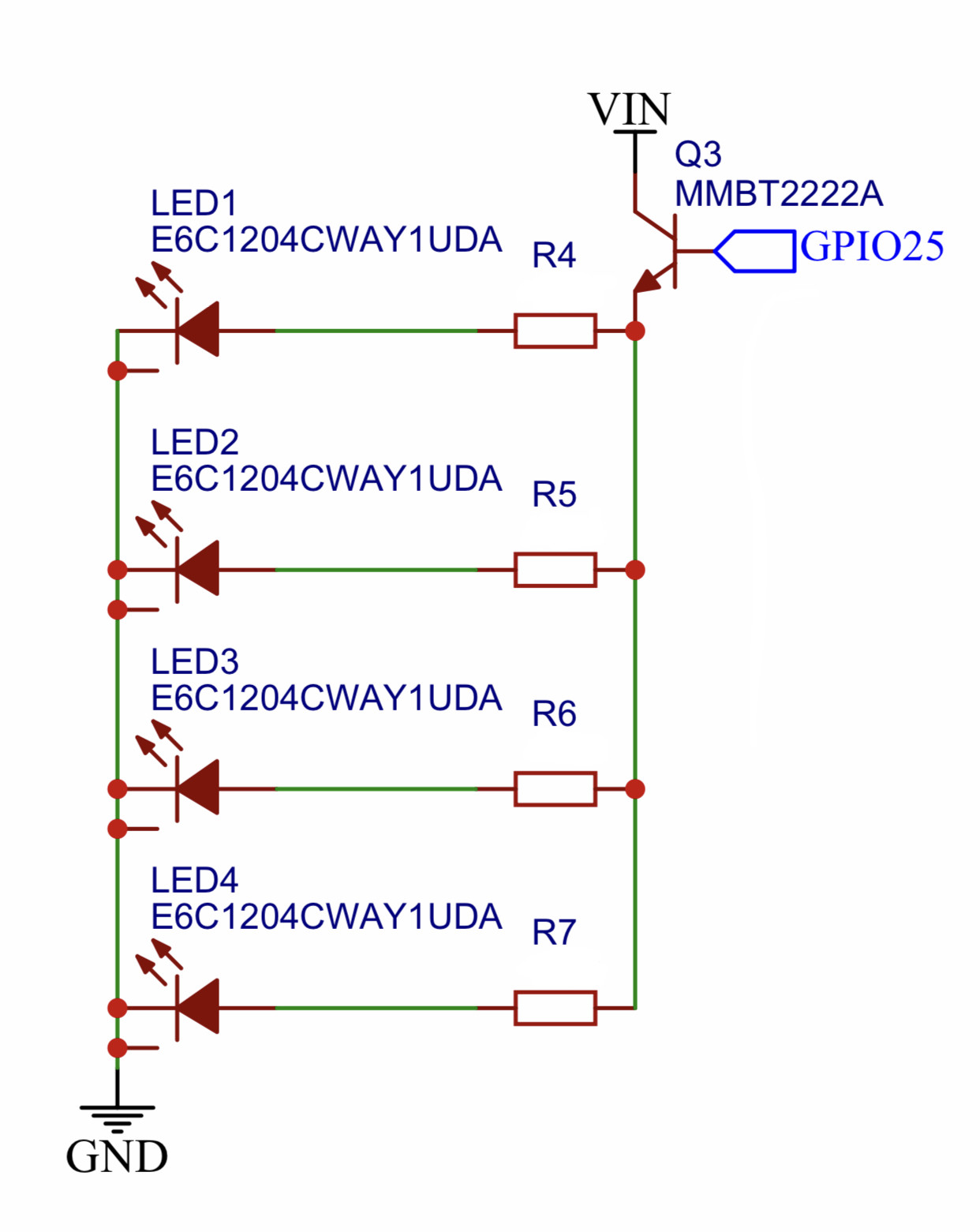
Circuit Diagram

If VIN measures 4.5-5 V, with the base either 0 V or 3.3 V, emitter at 2.6 V, I’m getting ~24 ohms needed to limit the LEDs to 25 mA each (100 mA total). This is assuming 700 mV BE drop.

Does this work with saturation and everything that entails this configuration? I'm still very new to this, but I'm trying to setup the transistor as a current amplifier so that the GPIO pin stays well below 12 mA and the fluctuating unregulated VIN can be used to feed to current for the LED load.

\$\endgroup\$
2
  • 1
    \$\begingroup\$ Does this work with saturation Actually the NPN transistor will not operate in saturation mode, it will work more like a regulator. The advantage of that is that the voltage across LED + resistor is regulated (to 2.6 V) which means that the current though the LEDs will remain fairly constant as the battery voltage drops (as the batteries deplete). When the battery voltage drops below 3.3 V (that 1.1 V per cell) you might notice decreased brightness from the LEDs. But 1.1 V per cell means the cells are empty so that's OK. \$\endgroup\$ Commented Sep 10, 2019 at 7:06
  • \$\begingroup\$ Thank you very much \$\endgroup\$
    – crabbyone
    Commented Sep 10, 2019 at 22:19

1 Answer 1

1
\$\begingroup\$

If the LEDs drop 2.0 volts at 30 mA and the emitter produces 2.6 volts when driven by 3.3 volts at the base then the voltage across the LED series resistor is 0.6 volts and, with a current of 30 mA flowing, the resistance is 20 ohms.

With 25 mA of LED current, the forward volt drop of the LED might be a fraction below 2.0 volts but it will be a small fraction; possible 1.9 volts so, the modified resistance value will be 0.7 volts / 25 mA = 28 ohms. I'd choose a 27 ohm resistor.

Does this work with saturation and everything that entails this configuration?

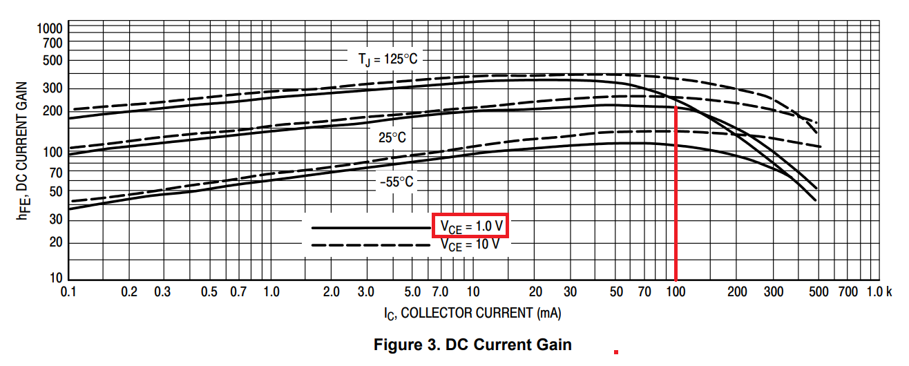
The BJT will not be saturating unless the Vin supply falls below about 3 volts. With the supply at 4.5 volts, the voltage across the collector-emitter will be about 2 volts and although it's close to approaching the region where saturation starts to begin, you can largely ignore those problems and rely on the normal beta value for the BJT.

MMBT2222 data sheet extract: -

enter image description here

With VCE at 1 volt and 100 mA flowing, the DC current gain is still pretty good at typically close to 200.

\$\endgroup\$
4
  • \$\begingroup\$ Thank you very much \$\endgroup\$
    – crabbyone
    Commented Sep 10, 2019 at 22:19
  • \$\begingroup\$ Aha another downvote - any explanations anyone? \$\endgroup\$
    – Andy aka
    Commented Sep 11, 2019 at 6:59
  • \$\begingroup\$ @Andyaka It breaks my heart that you take these so seriously. You have these quite often don't you? Is someone targeting you? \$\endgroup\$ Commented Sep 11, 2019 at 9:53
  • \$\begingroup\$ @Atizs yes, I think someone is and I'm not the sort of person who will let things like this drop so, don't let it break your heart too much LOL. \$\endgroup\$
    – Andy aka
    Commented Sep 11, 2019 at 10:01

Your Answer

By clicking “Post Your Answer”, you agree to our terms of service and acknowledge you have read our privacy policy.

Not the answer you're looking for? Browse other questions tagged or ask your own question.