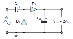
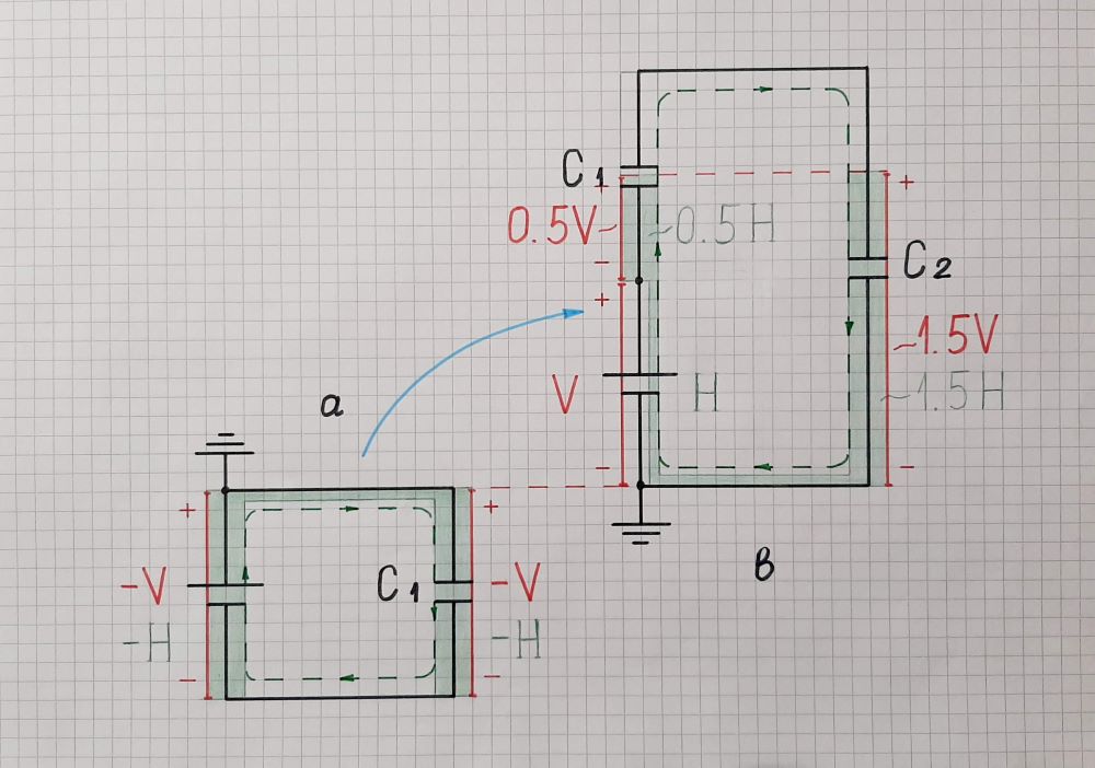
I've been having trouble trying to understand the circuit mentioned in the title, which you can see in the picture below.
Note that I'll be using the ideal diode model in my explanations. In case this is the reason I end up confused please let me know.
Let's see this step by step. During the negative half-cycle of the input, diode D1 is on and the capacitor C1 is being charged up to Vin (the maximum value of the input). Capacitor C2 is also being charged since with the charging of C1 D2 turns on but let's ignore this for now.
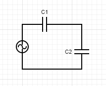
In most videos and websites I came across, the next crucial point is the positive half-cycle of the input. What I understand without doubt is that D1 will now be off. So we are left with the following circuit :
Now the part I don't understand is this :
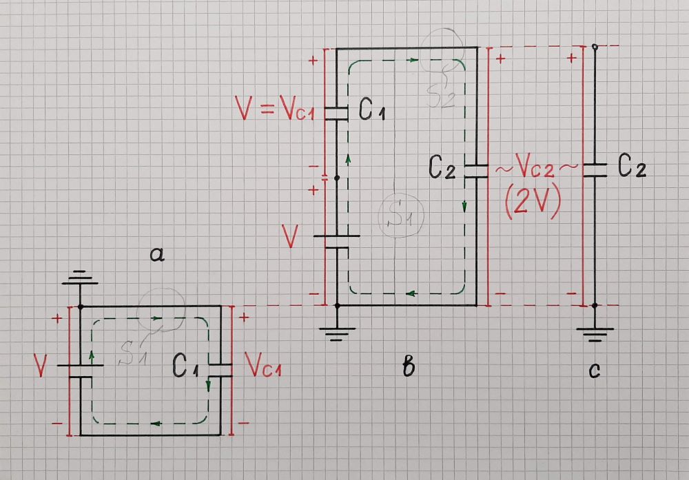
Because there is a voltage across capacitor C1 already equal to the peak input voltage, capacitor C2 charges to twice the peak voltage value of the input signal.
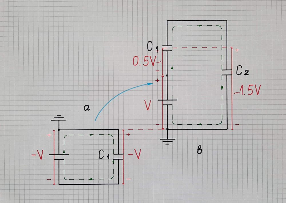
I cannot just accept this. I get that applying KVL with C1 charged will give me a C2 with a voltage of 2VIn. However, in order for C2 to charge, current is necessary. This means capacitor C1 will have to discharge in the process.
Also, KVL doesn't seem to hold if we apply it before C2 begins charging(it doesn't instantly charge to the 2Vin value) so this leads to even more confusion. Like, what happens if we connect a voltage source in series with a charged and a non-charged capacitor?
You can ignore this last question, I'm mostly concerned about how the voltage doubler works and I'm not happy with the explanations I find.

